

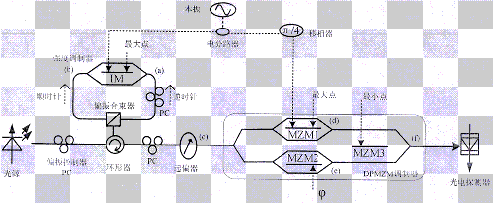
Device cascading embedded IM modulator Sagnac ring with DPMZM modulator so as to form 8-frequency multiplication millimeter wave
A modulator and millimeter wave technology, which is applied in electromagnetic wave transmission systems, optical fiber transmission, electrical components, etc., can solve the problems of reducing device performance, difficulty in electrical field devices, and difficulty in generating high-frequency, high-quality signals, etc., to reduce response The effect of frequency requirements, simple equipment, and strong practical operability
- Summary
- Abstract
- Description
- Claims
- Application Information
AI Technical Summary
Problems solved by technology
Method used
Image

Examples
Embodiment Construction
[0026] The embodiments of the present invention are described in detail below in conjunction with the accompanying drawings: this embodiment is implemented on the premise of the technical solution of the present invention, and detailed implementation methods and specific operating procedures are provided, but the protection scope of the present invention is not limited to the following The described embodiment:
[0027] Such as figure 1 As shown, in this embodiment, the device includes: a light source, a polarization controller, a Sagnac ring, a polarizer, a DPMZM modulator, a local oscillator signal source, an electrical splitter, a phase shifter and a photodetector, wherein the Sagnac ring is composed of It consists of circulator, polarization beam combiner and intensity modulator. The output port of the light source is connected to the Sagnac ring through the polarization controller, the Sagnac ring is connected to the polarizer through the polarization controller, the out...
PUM
 Abstract
Description
Claims
Application Information