Control method of detonation pipe for high-frequency pulse detonation engine

A technology of detonation engine and high-frequency pulse, which is applied in the direction of engine components, fuel control of turbine/propulsion device, mechanical equipment, etc. The working needs of the vibration engine and other issues can be achieved to achieve the effect of extending the life, reducing the load, and reducing the response frequency.

Inactive Publication Date: 2013-06-05
NORTHWESTERN POLYTECHNICAL UNIV
View PDF8 Cites 0 Cited by
  • Summary
  • Abstract
  • Description
  • Claims
  • Application Information

AI Technical Summary

Problems solved by technology

However, the current research level of high-frequency solenoid valves at home and abroad determines that high-frequency solenoid valves can only be made with a diameter below Φ2mm, which cannot meet the working needs of pulse detonation engines under large flow rates.
However, the electromagnetic valves that can meet the working flow requirements of pulse detonation engines generally do not have a high frequency, which has become a bottleneck factor that limits the research of pulse detonation engines and seriously restricts the subsequent development of pulse detonation engines.

Method used


Image

  • Control method of detonation pipe for high-frequency pulse detonation engine
  • Control method of detonation pipe for high-frequency pulse detonation engine
  • Control method of detonation pipe for high-frequency pulse detonation engine

Examples


Embodiment 1

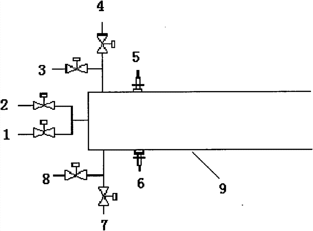
[0027] Refer to attached figure 1 , the detonation tube 9 of a high-frequency pulse detonation engine is connected with a first fuel inlet electromagnetic valve 1 and a second fuel inlet electromagnetic valve 2 at the fuel inlet of the detonation tube 9, and at the isolation gas inlet The first isolation gas inlet electromagnetic valve 3 and the second isolation gas inlet electromagnetic valve 4 are connected, the first oxidant inlet electromagnetic valve 7 and the second oxidant inlet electromagnetic valve 8 are connected at the oxidant inlet, and the detonation tube 9 is also connected A first igniter 5 and a second igniter 6 are horizontally oppositely installed on the detonation tube. The oxidizer inlet and the isolation gas inlet of the detonation tube 9 are relatively installed, and both are located in the middle of the igniter and the closed end of the detonation tube. The center of the closed end of the shock tube is axially air-intaked.

[0028] In this embodiment,...

Embodiment 2

[0035] The difference between the structure of the detonation tube 9 and that of Embodiment 1 is that the distance between the oxidant inlet and the isolation gas inlet and the closed end of the detonation tube is 1 times the inner diameter of the detonation tube; the distance between the spark plug and the closed end of the detonation tube 9 is 90 mm, that is, the detonation 3 times the inner diameter of the tube.

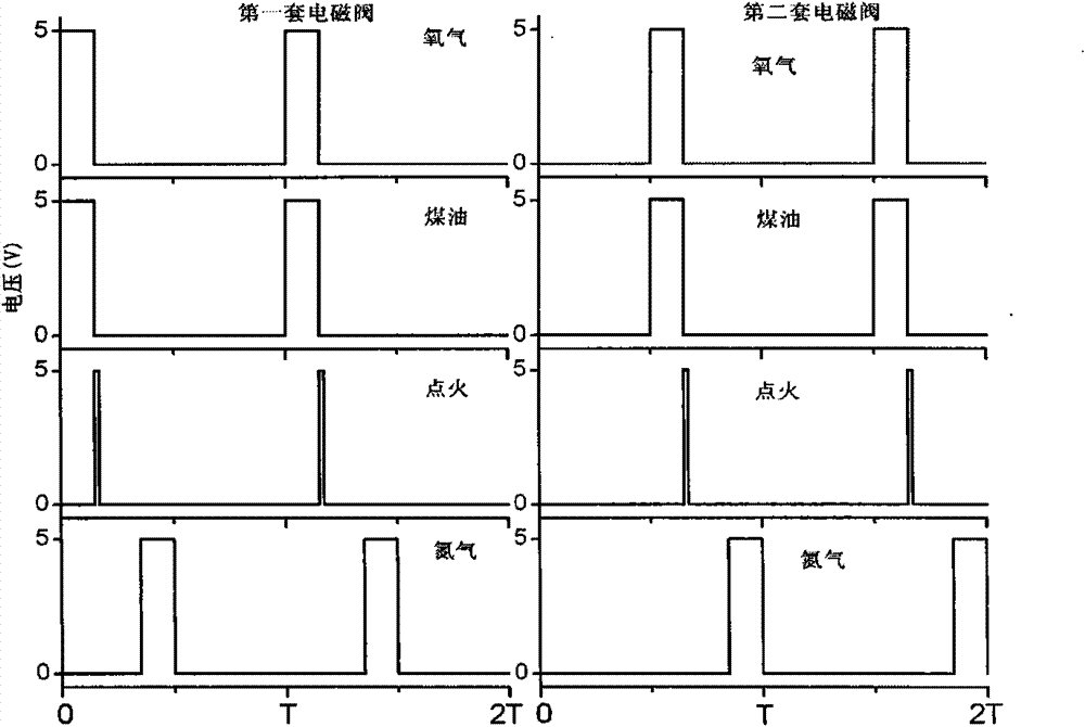
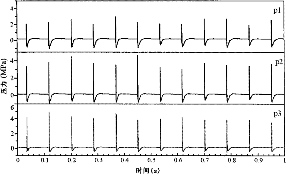
[0036] This embodiment is tested on a pulse detonation engine, and the control system outputs eight square wave signals to control two sets of solenoid valves and two igniters. In the first half of a control cycle, the first fuel inlet solenoid valve 1, the first oxidant inlet solenoid valve 7, the first igniter 5 and the first isolation gas inlet solenoid valve 3 work, and the first fuel inlet solenoid valve 1 And the duty cycle of the first oxidant inlet solenoid valve 7 is 0.3, the phase is 0°, the duty cycle of the first igniter 5 is 0.04, the phase is 108°, t...


PUM


Abstract

The invention provides a detonation pipe for a high-frequency pulse detonation engine and a control method thereof. The detonation pipe is characterized in that two fuel inlet solenoid valves are connected at a fuel inlet of the detonation pipe; two oxidant inlet solenoid valves are connected at an oxidant inlet of the detonation pipe; two insolated gas inlet solenoid valves are connected at an insolated gas inlet of the detonation pipe; and two igniters are mounted on the detonation pipe, wherein in one control period, a set of the solenoid valves are used for running and one igniter is usedfor igniting in the front half period and the other set of the solenoid valves are used for running and the other igniter is used for igniting in the latter half period. The invention can efficientlyincrease the work frequency of the pulse detonation engine and greatly decrease the demand on the solenoid valve response frequency. The solenoid valve which has the response frequency as half as thework frequency of the engine can be used, in order to decrease the load of the solenoid valve and help prolonging the service life of the solenoid valve.

Description

technical field [0001] The invention belongs to the technical field of engines, in particular to a detonation tube of a high-frequency pulse detonation engine and a control method thereof. Background technique [0002] Pulse Detonation Engine (PDE) is an unsteady propulsion system that uses pulse detonation waves to generate periodic impulses. Different from traditional engines, pulse detonation engines are intermittently working power devices based on detonation combustion. Therefore, how to quickly and reliably generate detonation waves in the detonation tube is the core issue in the design of pulse detonation engines, and it is also a key factor that determines the performance of pulse detonation engines. [0003] The research shows that the operating frequency of the pulse detonation engine has an important influence on the performance parameters of the pulse detonation engine. Ideally, the thrust of a pulse detonation engine increases linearly with the increase of ope...

Claims


Application Information

Patent Timeline
Patent Type & Authority Patents(China)
IPC IPC(8): F02K7/06F02C9/48
Inventor 范玮李建玲陈巍王可
Owner NORTHWESTERN POLYTECHNICAL UNIV
Why Eureka
Try Eureka