Eureka AIR delivers breakthrough ideas for toughest innovation challenges, trusted by R&D personnel around the world.

Moving target real-time positioning method based on visible light communication

A visible light communication and moving target technology, applied in the field of real-time positioning of moving targets based on visible light communication, can solve the problem of high energy consumption, reduce communication delay, facilitate real-time positioning, and reduce clock synchronization errors.

Active Publication Date: 2017-07-18
CHONGQING UNIV OF POSTS & TELECOMM
View PDF6 Cites 11 Cited by
  • Summary
  • Abstract
  • Description
  • Claims
  • Application Information

AI Technical Summary

Problems solved by technology

In order to solve the problem of indoor positioning and navigation, technology giants and research institutions have carried out a lot of research, such as assisted GPS (A-GPS) based on mobile communication network, pseudolite (Pseudolite), wireless local area network (WLAN), radio frequency tag (RFID) , Zigbee, Bluetooth (Bluetooth, BT), ultra-wideband radio (UltraWideBand, UWB), infrared positioning, computer vision positioning, geomagnetism, ultrasonic positioning and LED visible light positioning, etc. The use of WLAN and infrared positioning often requires the construction of complex positioning equipment. high energy consumption

Method used


Image

  • Moving target real-time positioning method based on visible light communication
  • Moving target real-time positioning method based on visible light communication
  • Moving target real-time positioning method based on visible light communication

Examples


Embodiment Construction

[0034] The preferred embodiments of the present invention will be described in detail below with reference to the accompanying drawings.

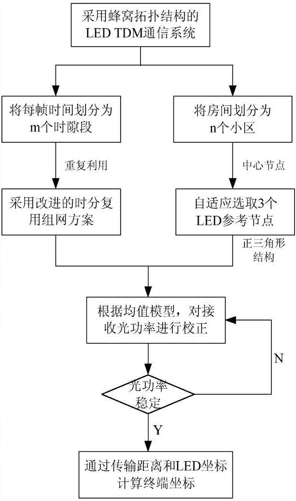
[0035] A real-time positioning method for moving targets based on visible light communication provided by the present invention combines mobile terminals such as mobile phones with a large indoor environment to achieve low energy consumption and high-precision indoor positioning, such as figure 1 shown, including the following steps:

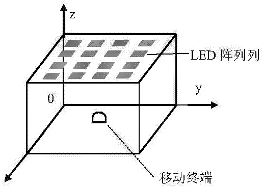
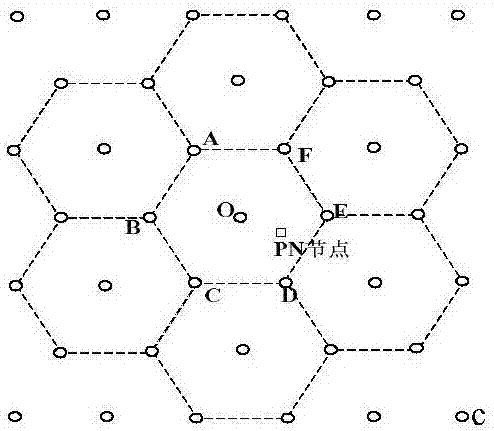
[0036] Step 1: Divide the m LED nodes in the room into n cells, increase the coverage of positioning, and utilize the high positioning accuracy of LEDs with equilateral triangle geometry to the greatest extent.

[0037] In order to meet high-precision real-time positioning, an improved time-division multiplexing networking system is adopted. A network source center node is selected in each cell, and the network source center node is selected to apply for a time slot segment from the gateway through competitio...


PUM


Abstract

The invention relates to a moving target real-time positioning method based on visible light communication, and belongs to the technical field of wireless communication. The moving target real-time positioning method based on visible light communication, which is provided by the invention, comprises the steps of: by adopting a cellular topological structure, partitioning indoor LED nodes into a plurality of cells, selecting network source center nodes, applying time slot periods by competition, and sending optical signals according to time slots by LEDs; by a terminal, adaptively selecting three LED reference nodes; by adopting an RSS positioning algorithm, according to receiving optical power, calculating transmission distances from the LED reference nodes to the terminal; and carrying out correction on the optical power of a receiving end by adopting a mean value model, and finally, by coordinates and the transmission distances of the LED reference nodes, calculating coordinates of the terminal so as to implement indoor positioning. The method solves the contradiction of excessively large frame length and excessively large number of LED nodes, reduces waiting time delay of a communication system to the greatest degree, solves the problem of influence of channel attenuation caused by LED light shielding and terminal movement on positioning, and has the advantages of low energy consumption, high accuracy, no electromagnetic interference and the like.

Description

technical field [0001] The invention belongs to the technical field of wireless communication, in particular to a real-time positioning method of a moving target based on visible light communication. Background technique [0002] In areas such as large indoor parking lots and shopping malls, indoor positioning technology has broad application prospects. It can locate mobile terminals, obtain user behavior data, and help users specify routes and push information. [0003] Outdoors, location information is generally obtained through GPS global positioning satellites. The GPS device estimates the current position of the receiving terminal by receiving signals from four or more satellites, which can achieve high-precision positioning. GPS indoor positioning, due to the obstruction of the signal by the wall, the positioning error usually reaches several meters to tens of meters. In order to solve the problem of indoor positioning and navigation, technology giants and research i...

Claims


Application Information

Patent Timeline
Patent Type & Authority Applications(China)
IPC IPC(8): H04W64/00G01S5/02H04B10/116
CPCG01S5/02H04B10/116H04W64/006Y02D30/70
Inventor 陈勇李逸超刘焕淋
Owner CHONGQING UNIV OF POSTS & TELECOMM
Why Eureka
Eureka Blog
Learn More