Sterilizing device for shaping medical devices

A kind of technology of medical device and sterilization device

Inactive Publication Date: 2017-07-21
王志强
0 Cites 7 Cited by

AI-Extracted Technical Summary

Problems solved by technology

[0005] Aiming at the deficiencies of the prior art, the present invention provides a medical instrument disinfection device for plastic surgery, which solves the problem that the efficiency of the existing general disinfection...

Method used

And, the cooperation between partition block (19), notch (20) and conveyer belt (21) is used, and the medical equipment that pours out can drop on the partition block (19), and medical equipment is from partition block ( The inclined upper surface of 19) slides down onto the conveyor belt (21), and is transmitted to the outside through the conveyor belt (21), which effectively reduces the work intensity of medical personnel and provides greater convenience for the work of medical personnel.
And, utilize driving motor (15) to drive guide gear (2) to rotate by driving wheel (16), driven wheel (17) and transmission belt (18), utilize guide gear (2) to drive connecting chain (3) again move, so that the connecting chain (3) can drive the hydraulic telescopic main rod (5) to move, effectively improving the efficiency of disinfection.
This medical equipment disinfection device for plastic surgery effectively improves the disinfection efficiency of medical equipment, can sterilize large quantities of medical equipment more quickly, effectively reduces the work intensity of medical personnel, by guiding gear (2), connecting Chain (3), driving motor (15), driving wheel (16), driven wheel (17) and driving belt (18) are used in conjunction with each other, and driving motor (15) is used to pass driving wheel (16), driven wheel (17) and drive belt (18) drive guide gear (2) to rotate, utilize guide gear (2) to drive connecting chain (3) to move again, make connecting chain (3) drive hydraulic telescopic main bar (5) to move, effectively Improve the efficiency of disinfection, through the hydraulic telescopic main rod (4), connecting rod (5), movable connecting rod seat (6), square connecting frame (7), movable connecting ring (8), left connecting half frame (9) , the rig...

Abstract

The invention discloses a medical instrument disinfection device for plastic surgery, which comprises a disinfection box. Four guide gears are evenly distributed inside the disinfection box. Mandrel shafts are arranged on the front and back sides of the guide gears. One of the four guide gears is There is a connecting chain around the connecting chain, and the outer side of the connecting chain is provided with equidistantly arranged hydraulic telescopic main rods. The end of the hydraulic telescopic main pipe away from the connecting chain is provided with a connecting rod, and the end of the connecting rod far away from the hydraulic telescopic main rod is provided with a movable connecting rod seat. A square connecting frame is arranged on the end of the movable connecting rod seat away from the connecting rod, and movable connecting rings are arranged on the left and right sides of the bottom of the square connecting frame. The medical instrument disinfection device for plastic surgery effectively improves the disinfection efficiency of medical instruments, can more quickly sterilize a large number of medical instruments, and effectively reduces the work intensity of medical personnel.

Application Domain

Technology Topic

Image

  • Sterilizing device for shaping medical devices
  • Sterilizing device for shaping medical devices

Examples

  • Experimental program(1)

Example Embodiment

[0025] The technical solutions in the embodiments of the present invention will be clearly and completely described below with reference to the accompanying drawings in the embodiments of the present invention. Obviously, the described embodiments are only a part of the embodiments of the present invention, but not all of the embodiments. Based on the embodiments of the present invention, all other embodiments obtained by those of ordinary skill in the art without creative efforts shall fall within the protection scope of the present invention.
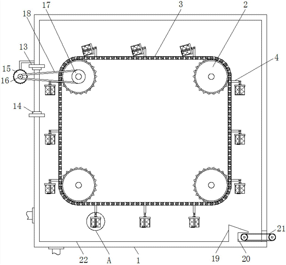
[0026] see Figure 1-2 , the present invention provides a technical solution: a sterilizing device for plastic medical instruments, comprising a sterilization box (1), the bottom of the left side of the sterilization box (1) is provided with a water inlet pipe that communicates with it, and the interior of the sterilization box (1) Four guide gears (2) evenly distributed are provided, the guide gears (2) are connected with the sterilization box (1) through the mandrel, the mandrel is arranged on the front and the back of the guide gear (2), and the four guide gears (2) ) is surrounded by a connecting chain (3), the outer side of the connecting chain (3) is provided with hydraulic telescopic main rods (4) arranged at equal distances, and the end of the hydraulic telescopic main pipe away from the connecting chain (3) is provided with a connecting rod (5) , the end of the connecting rod (5) away from the hydraulic telescopic main rod (4) is provided with a movable connecting rod seat (6), and the end of the movable connecting rod seat (6) away from the connecting rod (5) is provided with a square connecting frame (7), The left and right sides of the bottom of the square connection frame (7) are provided with movable connection rings (8), and the movable connection ring (8) on the left side of the bottom of the square connection frame (7) is provided with the movable connection ring (8). The left connection half frame (9) of the movable connection, the movable connection ring (8) on the right side of the bottom of the square connection frame (7) is provided with the movable connection ring (8) and the right connection half frame (10) of the movable connection; Both the connecting half frame (9) and the right connecting half frame (10) are provided with a sterilizing mesh partition (23), and the disinfection mesh partition (23) on the left connecting half frame (9) is distributed on the left connecting half frame (9). ) on the left side, bottom front and back side, the sterilizing mesh spacer (23) on the right connecting half frame (10) is distributed on the right side, bottom front and back of the right connecting half frame (10), and the left connecting half frame (9) ) and the right connecting half frame (10) is provided with a hydraulic discharging telescopic rod (11), and the hydraulic discharging telescopic rod (11) is located inside the bottom of the left connecting half frame (9) and the right connecting half frame (10), Both ends of the hydraulic unloading telescopic rod (11) are connected to the left connecting half frame (9) and the right connecting half frame (10) respectively through the unloading movable seat (12), and the hydraulic telescopic main rod (4) is connected to the connecting rod ( 5), between the connecting rod (5) and the movable connecting rod seat (6), and between the hydraulic discharging telescopic rod (11) and the discharging movable seat (12) are all movably connected by pins.
[0027] The left side of the sterilization box (1) is provided with a feeding port, the bottom and the top of the feeding port are provided with air curtain machines (13), and the opposite sides of the two air curtain machines (13) are provided with strip-shaped air outlets (14), the left side of the sterilization box (1) is provided with a drive motor (15), the output shaft on the front of the drive motor (15) is connected with the drive shaft through a coupling, and one end of the front of the drive shaft is provided with a driving wheel (16) , a driven wheel (17) is provided on the mandrel on the front of the guide gear (2) in the upper left corner of the interior of the sterilization box (1), and the driving wheel (16) is connected with the driven wheel (17) through a transmission belt (18).
[0028] The right side of the top of the inner bottom wall of the sterilization box (1) is provided with a dividing block (19) integrally formed therewith, and the angle between the upper surface of the dividing block (19) and the horizontal plane is forty to fifty degrees, and the dividing block (19) The top of 19) is inclined downward to the right, a notch (20) is provided on the bottom of the right side of the partition block (19), and a discharge port is provided on the bottom of the right side of the sterilization box (1). The conveyor belt (21), the left end of the transmission belt extends leftward to the interior of the notch (20), and a sterilization pool (22) is formed between the partition block (19) and the left side wall of the sterilization box (1). The sterilization box (1) The left side of the bottom of ) is provided with a drainage pipe communicated with the disinfection tank (22).
[0029]The sterilizing device for orthopedic medical devices effectively improves the sterilization efficiency of medical devices, can sterilize large quantities of medical devices more quickly, and effectively reduces the work intensity of medical personnel. ), the driving motor (15), the driving wheel (16), the driven wheel (17) and the transmission belt (18) are used in cooperation with each other, and the driving motor (15) is used to pass the driving wheel (16), the driven wheel (17) and the transmission belt (18) drive the guide gear (2) to rotate, and then use the guide gear (2) to drive the connecting chain (3) to move, so that the connecting chain (3) can drive the hydraulic telescopic main rod (5) to move, effectively improving the disinfection effect. The efficiency is achieved through the hydraulic telescopic main rod (4), the connecting rod (5), the movable connecting rod seat (6), the square connecting frame (7), the movable connecting ring (8), the left connecting half frame (9), the right connecting The half frame (10), the hydraulic discharge telescopic rod (11) and the discharge movable seat (12) are used in cooperation with each other, and the medical personnel put the medical equipment to be sterilized into the left connecting half frame (9) and the right connecting half Between the frames (10), the connecting chain (3) drives the downward movement. During the downward movement, the medical personnel can extend the hydraulic telescopic main rod (4) so ​​that the medical equipment can be placed in the disinfection tank (22). After the disinfection is completed, medical personnel can extend the hydraulic discharge telescopic rod (11), so that the medical equipment between the left connecting half frame (9) and the right connecting half frame (10) can be dumped out , the operation is more convenient, and a large number of medical instruments can be sterilized. 14) Blow air to the outside, and use the wind blown by the air curtain machine (13) to isolate the interior of the disinfection box (1) from the outside world, effectively avoiding the pollution to the outside world. When used in cooperation with each other (21), the poured medical instruments can fall on the partition block (19), and the medical instruments slide down from the inclined upper surface of the partition block (19) to the conveyor belt (21), and pass through the conveyor belt (21). The conveyor belt (21) is transmitted to the outside world, which effectively reduces the work intensity of the medical staff and provides greater convenience for the work of the medical staff.
[0030] To sum up, the device for sterilizing medical devices for plastic surgery effectively improves the sterilization efficiency of medical devices, can sterilize large quantities of medical devices more quickly, and effectively reduces the work intensity of medical personnel.
[0031] In addition, the drive motor (15) is used to drive the guide gear (2) to rotate through the driving wheel (16), the driven wheel (17) and the transmission belt (18), and then the guide gear (2) is used to drive the connecting chain (3) to move, so that the The connecting chain (3) can drive the hydraulic telescopic main rod (5) to move, which effectively improves the efficiency of disinfection.
[0032] In addition, the medical personnel put the medical equipment to be sterilized between the left connecting half frame (9) and the right connecting half frame (10), and are driven to move downward by the connecting chain (3). Personnel can extend the hydraulic telescopic main rod (4) so ​​that the medical equipment can be sterilized inside the disinfection tank (22). The medical instruments between the connecting half frame (9) and the right connecting half frame (0) can be poured out, the operation is more convenient, and a large quantity of medical instruments can be sterilized.
[0033] In addition, the air curtain machine (13) can blow air to the outside through the strip-shaped air outlet (14), and the interior of the disinfection box (1) is isolated from the outside by the wind blown by the air curtain machine (13), thereby effectively avoiding pollution to the outside world. .
[0034] In addition, due to the cooperation between the dividing block (19), the recess (20) and the conveyor belt (21), the poured medical instruments can fall on the dividing block (19), and the medical instruments can be removed from the dividing block (19). The inclined upper surface slides down onto the conveyor belt (21), and is transmitted to the outside through the conveyor belt (21), which effectively reduces the work intensity of medical personnel and provides greater convenience for medical personnel to work.
[0035] It should be noted that, herein, the terms "comprising", "comprising" or any other variation thereof are intended to encompass non-exclusive inclusion, such that a process, method, article or device comprising a series of elements includes not only those elements, It also includes other elements not expressly listed or inherent to such a process, method, article or apparatus. without more restrictions. An element defined by the phrase "comprising an... does not preclude the presence of additional identical elements in a process, method, article or apparatus comprising said element".
[0036] Although embodiments of the present invention have been shown and described, it will be understood by those skilled in the art that various changes, modifications, and substitutions can be made in these embodiments without departing from the principle and spirit of the invention and modifications, the scope of the present invention is defined by the appended claims and their equivalents.

PUM

no PUM

Description & Claims & Application Information

We can also present the details of the Description, Claims and Application information to help users get a comprehensive understanding of the technical details of the patent, such as background art, summary of invention, brief description of drawings, description of embodiments, and other original content. On the other hand, users can also determine the specific scope of protection of the technology through the list of claims; as well as understand the changes in the life cycle of the technology with the presentation of the patent timeline. Login to view more.

Similar technology patents

Movable intelligent disinfecting robot

Owner:青岛海沃医疗用品有限公司

Gas water mixing box

InactiveCN102145263AMix thoroughlyImprove disinfection efficiencyFlow mixersMixing methodsOzone layerEngineering
Owner:佛山市好源来环保科技有限公司

Classification and recommendation of technical efficacy words

  • Improve disinfection efficiency
  • Reduce work intensity

Intelligent answering method and system

InactiveCN104679910AImprove Smart Reply AccuracyReduce work intensitySpecial data processing applicationsAlgorithmDegree of similarity
Owner:BEIJING ZHICHI BOCHUANG TECH

Fiber opener

InactiveCN102586956AReduce work intensityReduce equipment costFibre cleaning and opening machine combinationsFibre cleaning/opening machinesEngineeringStructural engineering
Owner:常熟市伟成非织造成套设备有限公司
Why Eureka
Try Eureka