Self-excited air granule conveying device

A conveying device and self-excited technology, which is applied in the direction of conveying bulk materials, conveyors, transportation and packaging, etc., can solve the problems of poor energy saving effect, reduce air conveying speed and pipeline wear, facilitate suspension and acceleration, reduce The effect of pressure loss

Active Publication Date: 2017-07-21
JIANGSU UNIV OF TECH
View PDF8 Cites 3 Cited by
  • Summary
  • Abstract
  • Description
  • Claims
  • Application Information

AI Technical Summary

Problems solved by technology

[0004] In order to solve the defect of poor energy-saving effect existing in the pri

Method used


Image

  • Self-excited air granule conveying device
  • Self-excited air granule conveying device
  • Self-excited air granule conveying device

Examples


Example Embodiment

[0022] The preferred embodiments of the present invention will be described in detail below with reference to the accompanying drawings.

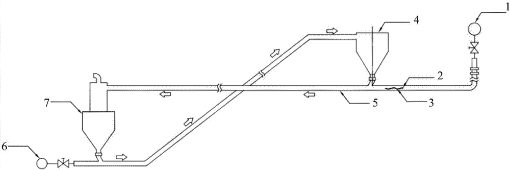
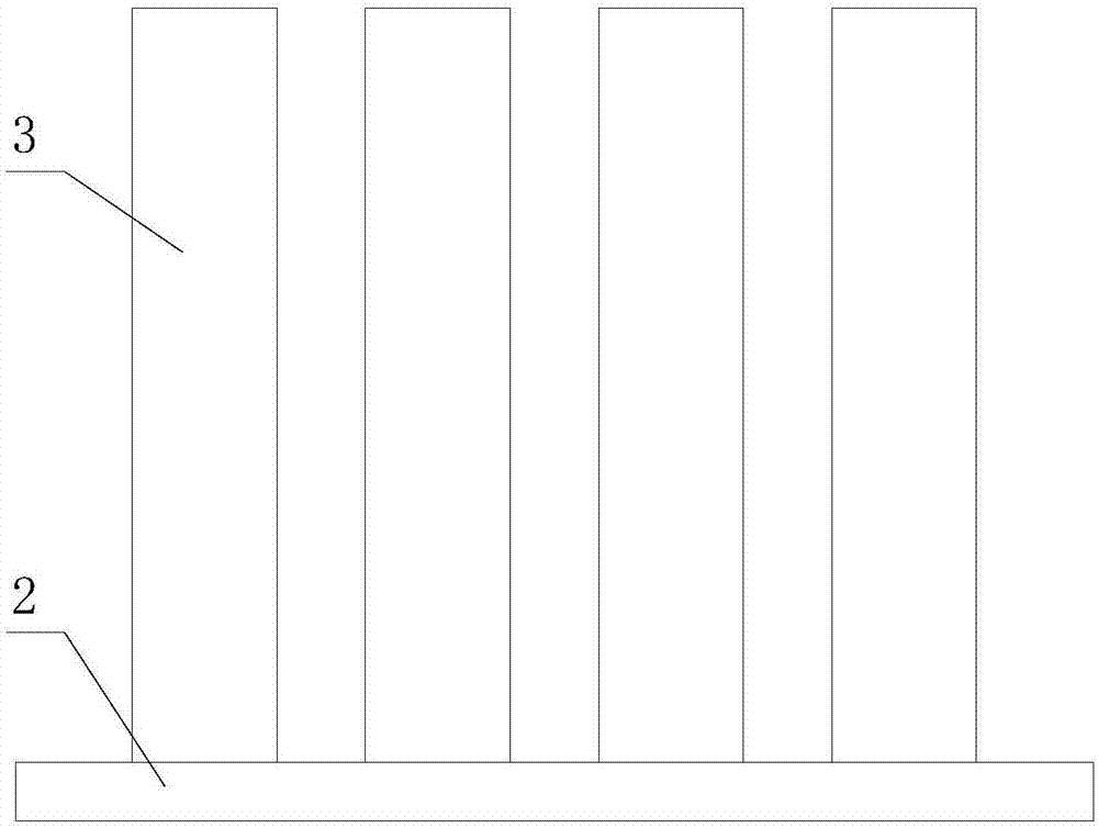
[0023] In order to achieve the purpose of the present invention, such as Figure 1 to Figure 2 As shown, in one of the embodiments of the present invention, a self-energizing air particle conveying device is provided, which includes a particle conveying pipe 5, a first blower 1, a second blower 6, a flexible spoiler assembly, a separator 7 and a feeding tank 4. The particle conveying pipe 5 is a cylindrical structure with an axial cavity. The first blower 1 and the separator 7 are respectively connected to the axial ends of the particle conveying pipe 5, and the feeding tank 4 is connected to the particle conveying pipe 5. Set close to the first blower 1, a circulating material pipe is arranged between the separator 7 and the feeding tank 4, the second blower 6 is connected to the circulating material pipe, and the flexible turbulence component...


PUM

PropertyMeasurementUnit
Densityaaaaaaaaaa

Abstract

The invention provides a self-excited air granule conveying device. The self-excited air granule conveying device comprises a granule conveying pipe, a first air blower, a second air blower, a flexible turbulence assembly, a separator and a feeding tank. The flexible turbulence assembly is arranged inside the granule conveying pipe and is close to a discharging opening of the feeding tank. The flexible turbulence assembly comprises a fin rod and multiple flexible fins. The flexible fins are evenly arranged on the fin rod in the length direction of the fin rod. The two axial ends of the fin rod are arranged in an axial cavity of the granule conveying pipe. By the adoption of the self-excited air granule conveying device, under the drive of turbulent air flow, granules flow along the granule conveying pipe, and extra energy is not needed; the flexible fins have the enhancement function on the speed of the vertical air flow so that the granules can more easily suspend and accelerate, and the pressure loss of the system can be reduced; and air flow oscillation caused by the flexible fins changes the movement features of the granules, so that low-frequency large-scale granule flow is formed beneficially, and the air conveying speed and pipe wear can be reduced.

Description

technical field [0001] The invention relates to a self-exciting air particle conveying device. Background technique [0002] Pneumatic conveying widely exists in energy, chemical, food, pharmaceutical and other industrial fields. According to different process requirements, pneumatic conveying can be divided into dense phase conveying and dilute phase conveying. In the process of dense phase transportation, its transportation stability is poor, and it is easy to produce the imagination of pipeline blockage and vibration. In industrial practice, dilute-phase conveying is more widely used. In the process of dilute-phase conveying, higher conveying speed leads to additional energy consumption and lower conveying efficiency. In addition, because particles are carried by high-speed gas, particles and The collision between the particles and the pipe wall will easily lead to serious wear of the conveying pipeline and the reduction of the quality grade of the conveying particles. ...

Claims


Application Information

Patent Timeline
IPC IPC(8): B65G53/58
CPCB65G53/58B65G2201/042
Inventor 张丹卢雅琳周健郑焱朱圣清
Owner JIANGSU UNIV OF TECH
Why Eureka
Try Eureka