Power system of cam rotor internal combustion engine

An internal combustion engine and power system technology, applied in the directions of internal combustion piston engine, combustion engine, rotary piston engine, etc., can solve the problems of limited scalability of triangular rotor internal combustion engine structure, difficult to improve rotor shaft torque, and high processing requirements for core parts , to achieve the effect of short motion transmission link, simple structure and large parameter range

Active Publication Date: 2017-07-21
DALIAN UNIV OF TECH
View PDF5 Cites 3 Cited by
  • Summary
  • Abstract
  • Description
  • Claims
  • Application Information

AI Technical Summary

Problems solved by technology

However, there are still key problems such as high processing requirements for core parts, too sensitive to wear, difficult adjustment of compression ratio, low thermal efficiency, etc., and it is still difficult to improve the combustion utilization rate
At the same time, similar to the piston internal combustion engine, the scalability of the triangular rotor internal combustion engine structure is also limited
In addition, when the expansion force generated by the fuel is converted into the power of the output shaft, there are natural defects in the transmission of force
Although the expansion force can push the rotor to rotate, it is difficult to increase the torque of the resultant force on the rotor shaft, and the proportion of internal friction is also too high

Method used


Image

  • Power system of cam rotor internal combustion engine
  • Power system of cam rotor internal combustion engine
  • Power system of cam rotor internal combustion engine

Examples


Embodiment 1

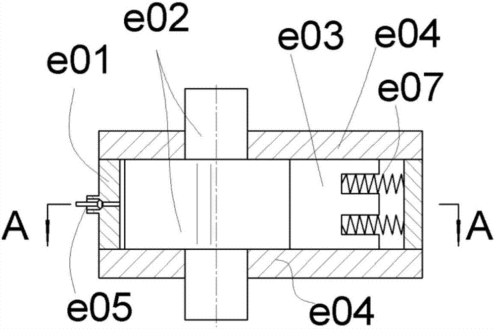
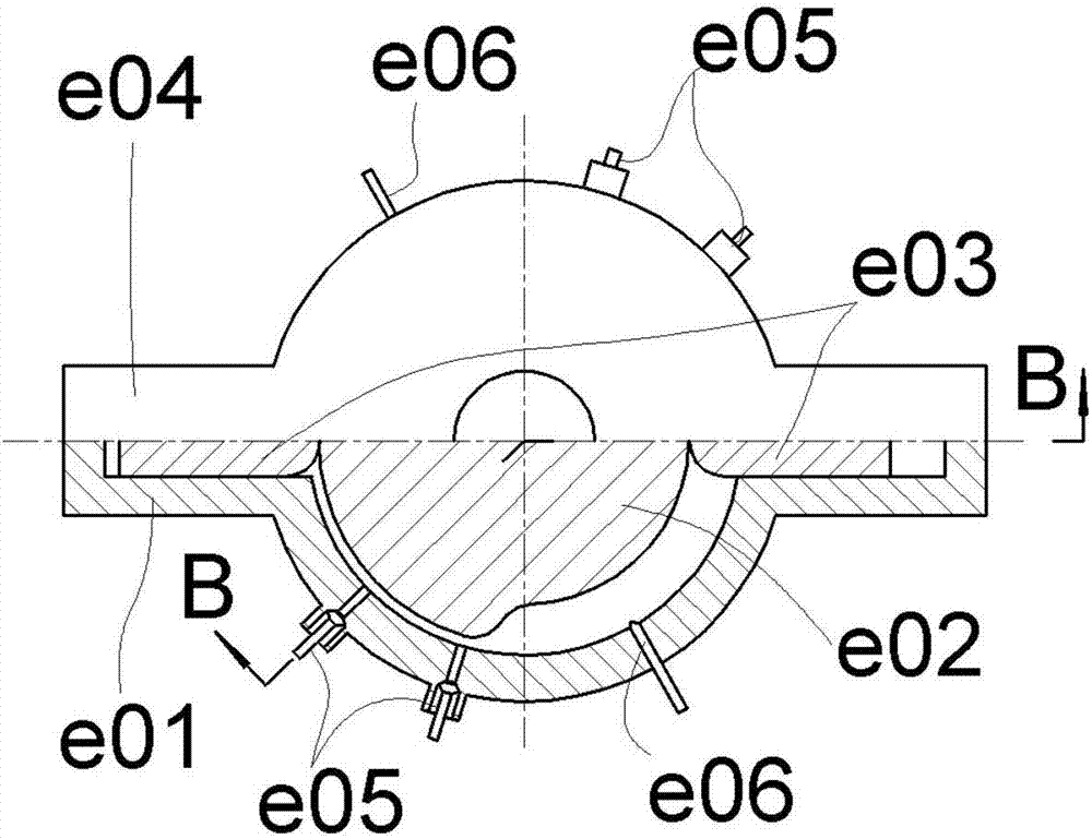
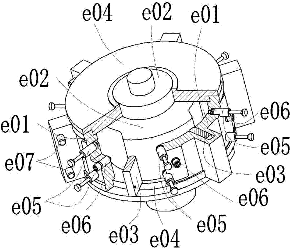
[0038] See figure 1 and figure 2 , figure 1 is the front view of a basic structure, and its top view corresponds to the attached figure 2 , and correspond to figure 2 The B-B profile, figure 2 correspond figure 1 The A-A profile. The rotor housing e01 has an inner cylindrical surface, and the cam is an outer contour disc cam with a section of far rest area and a section of near rest area, which is integrated with the rotary shaft to form the rotor e02. The far rest area and the near rest area are both close to 180°. The cam follower is the straight-moving slider e03, the number is 2, the slider e03 is installed in the sliding radial chute in the rotor chamber, and the spring e07 is used to realize force closure. Due to the small number of sliders, no slider escapement is added . The end member e04 is sealed and fixed with the rotor chamber and forms a dynamic seal with the end surface of the cam. There is a gap between the far resting area of ​​the cam and the inner...

Embodiment 2

[0041] See image 3 In this example, on the basis of the structure of Embodiment 1, the number of cam follower sliders e03 is increased to 6, uniformly distributed in the circumferential direction, and a slider escapement is set; the cam profile on the rotor e02 is far from the rest area and near The rest area is increased into two sections, which are arranged symmetrically in the circumferential direction. The arc length and centripetal angle of the far rest section are about 70°, slightly larger than the corresponding centripetal angles of the two adjacent sliders, and the centripetal angles of the near rest area are about 90°. . Sealing structure relation is the same as previous example, no longer repeats. The sliding block groove and the end member e04 also form an independent sealing chamber, which can be fed with compressed air or hydraulic oil to realize force sealing between the sliding block and the cam profile; the intake and exhaust ports e05 with valves and the ig...

Embodiment 3

[0058] See Figure 5 , the inner profile cam and the inner cylindrical surface shell are combined to form the inner profile cam rotor e01. The inner profile cam is a straight generatrix disc shape, with two sections of near rest area and two sections of far rest area, symmetrically arranged in the circumferential direction, and the arc length of the near rest section The centripetal angle is about 70°, and the centripetal angle of the far rest zone is about 90°. The cam follower pendulum e03 is installed on the center fixing frame e02 of the outer cylindrical surface, and the number of pendulum pieces is 6 evenly distributed, that is, the arc length of the near-rest segment and the centripetal angle are slightly larger than the centripetal angles between adjacent pendulum pieces. There is a gap between the near-rest section of the inner contour cam and the outer cylindrical surface of the central fixed frame e02, and the upper and lower end members e04 are sealed and fixed wit...


PUM


Abstract

The invention discloses a power system of a cam rotor internal combustion engine, belongs to the field of engines, and relates to a rotor internal combustion engine. The power system uses cams and multiple cam driven pieces to form a cam mechanism, and to form multiple sealed working cavities, peripherally distributed, with inner cavity components, outer rotating surface components and end components; the sealed working cavities change the volumes along with relative rotation of the cams and the cam driven pieces to match valves to finish four processes of intake, compression, acting and exhaust of the Otto cycle therein; and chemical energy generated by gas combustion is directly converted to mechanical energy in a rotor fixed-shaft rotating form. The power system discards a crankshaft of a piston engine; high-pressure gas directly pushes rotor fixed shafts to rotate and to output power; the structure is simple; and the parameter adjusting range is wide. The power system is liable to realize flexible control, or even can realize forward and reverse rotation under control of an additional cam driven piece encapement device; and compared with power systems of a piston internal combustion engine and a triangular rotor internal combustion engine, the power system of the cam rotor internal combustion engine has multiple prominent advantages.

Description

technical field [0001] The invention belongs to the field of engines and relates to a rotary internal combustion engine. Background technique [0002] The piston internal combustion engine is the earliest internal combustion engine that came out. Its characteristic is that the piston makes a reciprocating linear motion in the cylinder, and the output of the crankshaft rotary motion is realized through the crank slider mechanism. Within two weeks of crankshaft rotation, the cylinder completes a complete intake, compression, work, and exhaust four working processes, that is, the Otto cycle. It is generally believed that the piston internal combustion engine has the advantages of high thermal efficiency, compact structure, strong maneuverability, and easy operation and maintenance. It is even believed that the power device of the piston internal combustion engine, especially the mechanical structure, has reached the peak. However, the work process of the piston internal combu...

Claims


Application Information

Patent Timeline
Patent Type & Authority Applications(China)
IPC IPC(8): F02B53/00F02B55/16F01L1/06F01L9/10F01L9/20
CPCF01L1/06F02B53/00F02B55/16F02B53/06F02D13/0215F02D15/00F01C1/3566F01C21/0845F01C21/10Y02T10/12F01L9/10F01L9/20F01C21/18F01L1/047F01L1/08F01L1/22F01L2313/00
Inventor 孙守林卞永宁杨扬王琳张光临洪鹏飞
Owner DALIAN UNIV OF TECH
Why Eureka
Try Eureka