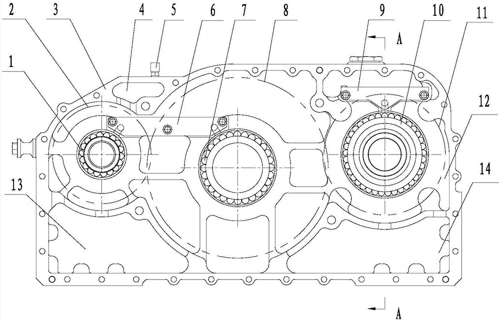
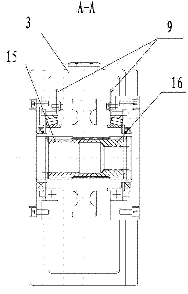
Power takeoff gearbox casing in direct connection with hydraulic pump, and power takeoff gearbox

A gear box and hydraulic pump technology, applied in the direction of gear lubrication/cooling, belt/chain/gear, transmission box, etc., can solve the problems of difficult to achieve performance and weight, optimal configuration of working space, high oil temperature support bearings, etc. Achieve the effect of avoiding unstable operation, avoiding excessive oil churning of gears, and realizing recycling.

Inactive Publication Date: 2017-07-21
泰安航天特种车有限公司
View PDF0 Cites 4 Cited by
  • Summary
  • Abstract
  • Description
  • Claims
  • Application Information

AI Technical Summary

Problems solved by technology

At present, the power take-off gearbox still has the problem of high oil temperature caused by excessive oil stirring of the gears, the lubrication problem of the support bearing, the oil injection problem of the vent port caused by the oil rejection of the gear in the narrow inner cavity, and the connection problem between the output gear of the power take-off and the device. To use conventional measures to solve the above problems, it is necessary to make concessions in space, volume and other aspects and to increase external equipment. It is difficult to achieve the optimal configuration of performance, weight and working space in all aspects.

Method used


Image

  • Power takeoff gearbox casing in direct connection with hydraulic pump, and power takeoff gearbox
  • Power takeoff gearbox casing in direct connection with hydraulic pump, and power takeoff gearbox

Examples


Embodiment Construction

[0031] It should be pointed out that the following detailed description is exemplary and intended to provide further explanation to the present application. Unless defined otherwise, all technical and scientific terms used herein have the same meaning as commonly understood by one of ordinary skill in the art to which this application belongs.

[0032] It should be noted that the terminology used here is only for describing specific implementations, and is not intended to limit the exemplary implementations according to the present application. As used herein, unless the context clearly dictates otherwise, the singular is intended to include the plural, and it should also be understood that when the terms "comprising" and / or "comprising" are used in this specification, they mean There are features, steps, operations, means, components and / or combinations thereof.

[0033] As introduced in the background technology, there are deficiencies in the prior art. In order to solve th...


PUM


Abstract

The invention discloses a power take-off gearbox casing and a power take-off gearbox directly connected to a hydraulic pump, which solve the problems of excessive oil stirring and high oil temperature of the gears in the prior art, and solve the problems caused by the excessive stirring of the gears. It solves the problem of heat dissipation caused by oil and solves the problem of lubrication of multiple bearings. The scheme is as follows: a power take-off gearbox casing directly connected to a hydraulic pump comprises that the power take-off gearbox casing is sequentially divided into a ventilation cavity, a main cavity, a first oil storage cavity and a second oil storage cavity through inner ribs, Oil passages are respectively provided between the main cavity and the two oil storage cavities, the ventilation cavity is isolated from the main cavity, and a first oil collecting pool is arranged above the position between the first bearing and the second bearing in the main cavity, and the third A second oil collecting pool is arranged above the bearing.

Description

technical field [0001] The invention relates to the field of vehicle power take-off technology, in particular to a power take-off gear box shell and a power take-off gear box directly connected to a hydraulic pump. Background technique [0002] The power take-off gearbox is an additional power output device installed outside the gearbox. It can obtain power from the power take-off interface of the gearbox, transfer case and other power transmission devices to provide power to the vehicle hydraulic pump, water pump, compressor, generator, Motor etc. provide power. At present, the power take-off gearbox still has the problem of high oil temperature caused by excessive oil stirring of the gears, the lubrication problem of the support bearing, the oil injection problem of the vent port caused by the oil rejection of the gear in the narrow inner cavity, and the connection problem between the output gear of the power take-off and the device. To use conventional measures to solve ...

Claims


Application Information

Patent Timeline
Patent Type & Authority Applications(China)
IPC IPC(8): F16H57/02F16H57/027F16H57/04
CPCF16H57/02F16H57/027F16H57/0471
Inventor 朱学斌韩欣欣张力存尤迪马元修赵娜刘庆
Owner 泰安航天特种车有限公司
Why Eureka
Try Eureka