Joint between housing and headlamp outer lens with glue-retaining ribs

A technology of ribs and outer lenses, applied in the field of lighting devices, can solve problems such as excessive accumulation, and achieve the effect of forming a cheap and simple solution

Inactive Publication Date: 2017-07-21
VALEO VISION SA
View PDF1 Cites 0 Cited by
  • Summary
  • Abstract
  • Description
  • Claims
  • Application Information

AI Technical Summary

Problems solved by technology

In fact, if said edge has a significant gradient with respect to the horizontal when the housing is oriented with its cavity and opening facing upwards, paste or liquid applied along the edge tends to flow and therefore accumulates in excess at certain points and leaves Insufficient coverage of other points

Method used


Image

  • Joint between housing and headlamp outer lens with glue-retaining ribs
  • Joint between housing and headlamp outer lens with glue-retaining ribs
  • Joint between housing and headlamp outer lens with glue-retaining ribs

Examples


Embodiment Construction

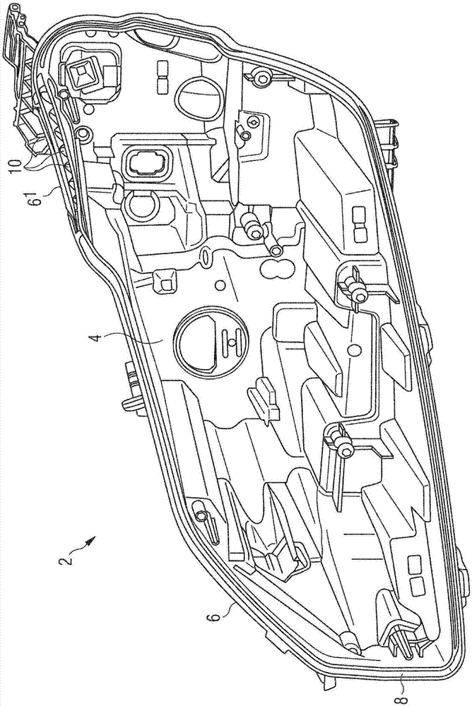
[0045] figure 1 A housing 2 for a lighting device, in this case a motor vehicle headlight, is shown. Such lighting devices can perform different functions, in particular low-beam or high-beam lighting, or signaling functions, such as direction indicators (blinkers), side lights or daytime running lights (DRL).

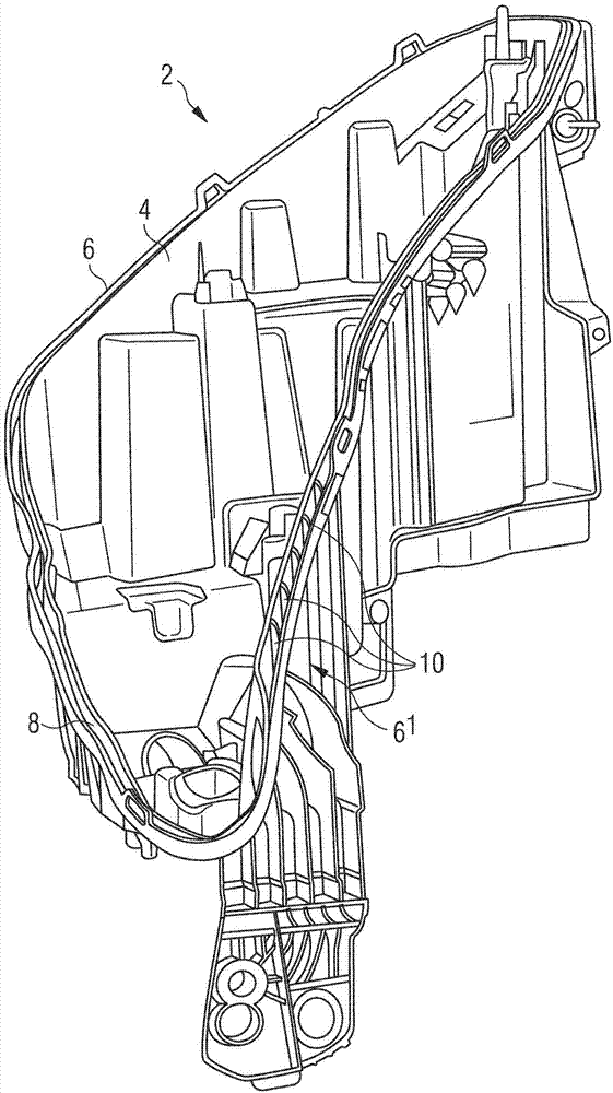
[0046] The housing 2 comprises a wall 4 which may have a complex shape. Said wall 4 forms a cavity designed to receive one or more lighting modules (not shown) designed to perform one or more of the aforementioned functions. These modules are well known to those skilled in the art.

[0047]The housing 2 also comprises a rim 6 delimiting the opening of the cavity. This edge is advantageously located on the wall 4 and, more specifically, at the end of said wall. The edge 8 advantageously forms a closed contour delimiting the opening of the cavity of the housing. Said edge 6 is designed to cooperate with the outer lens in order to close the cavity. The outer lens is...


PUM


Abstract

A housing (2) for a lighting device, in particular for a motor vehicle, comprising a wall (4) delimiting a cavity designed to receive one or more lighting modules, and an edge (6) that delimits the cavity and is designed to be glued to a corresponding rim of an outer lens designed to cover the cavity. The edge (6) has at least one portion (61) with ribs (10) that are designed to be in contact with the glue and are oriented such as to limit the flow of the glue during application of same. The invention also relates to a lighting device including the housing, and to a method for assembling the device.

Description

[0001] field of invention [0002] The invention relates to the field of lighting devices, in particular light signaling and / or lighting devices for motor vehicles. Background technique [0003] Published patent document FR 0187593 A1 discloses a method for assembling the outer lens of a motor vehicle headlight with its housing. The method involves gluing the rim of the outer lens to the corresponding rim of the housing, the contour of the rim and the edge creating an internal expansion volume due to the glue within the contour of the fitted parts. This document has a priority date of 1984, when headlight outer lenses usually have a geometry with an almost flat or at least almost flat bonding area. Then, when said edge is arranged horizontally, glue can be gradually applied along the edge of the housing without significant risk of glue flowing along said edge. [0004] Published patent document US 5,909,957 also discloses a method for fitting the outer lens of a motor vehicl...

Claims


Application Information

Patent Timeline
Patent Type & Authority Applications(China)
IPC IPC(8): F21S8/10F21V15/01F21V17/10F21W101/02F21W107/10
CPCF21V15/01F21V17/101F21S43/00F21W2107/10F21S41/28F21S41/29F21S43/27
Inventor 麦迪·马德兰伊恩史蒂夫·文森特蒂里·鲁斯莱吉恩-马克·格瑞瑟特
Owner VALEO VISION SA
Why Eureka
Try Eureka