Device for measuring thermal response time of thermocouple

A response time, thermocouple technology, applied in measurement devices, heat measurement, thermometer testing/calibration, etc., can solve problems such as high experimental overhead, inability to obtain thermal response time, temperature fluctuations, etc., to achieve compactness, labor saving, and convenience. effect of operation

Pending Publication Date: 2017-07-21
CHINA JILIANG UNIV
View PDF6 Cites 5 Cited by
  • Summary
  • Abstract
  • Description
  • Claims
  • Application Information

AI Technical Summary

Problems solved by technology

Among the existing measurement methods today, the traditional hot air tunnel method is complicated and expensive, and the experiment cost is relatively large; the rapid input method is also one of the commonly used methods, but the temperature of the constant temperature medium will be destroyed when the thermocouple is quickly put into the constant temperature medium. field, resulting in small temperature fluctuations and certain measurement errors; the problem with the instantaneous electric heating method is that it is impossible to obtain a more accurate temperature step signal; the defect of the shock tube method is that the temperature step platform maintains a short time, which is not enough The output response of the sensor reaches a steady-state value, making it impossible to obtain a reliable thermal response time

Method used


Image

  • Device for measuring thermal response time of thermocouple

Examples


Embodiment Construction

[0012] In order to make the object, technical solution and advantages of the present invention clearer, the present invention will be further described in detail below in conjunction with the accompanying drawings and embodiments. It should be understood that the specific embodiments described here are only used to explain the present invention, not to limit the present invention.

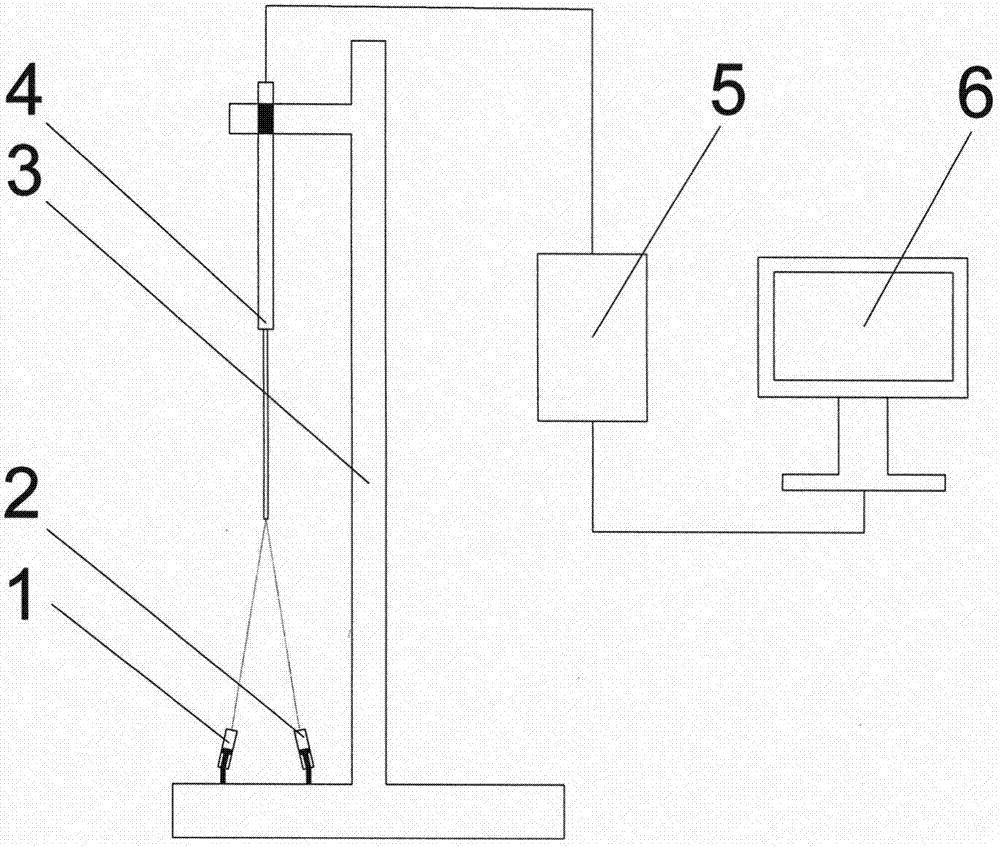
[0013] see figure 1 . A device for measuring the thermal response time of a thermocouple, comprising a high-power laser A1, a high-power laser B2, a fixing device 3, a thermocouple 4, a data acquisition card 5, and a computer 6. The high-power laser A1 and the high-power laser B2 are fixed on the lower part of the fixture 3, and the thermocouple 4 is fixed on the top of the fixture 3, and the reference terminal wire of the thermocouple 4 is connected to the input end of the data acquisition card 5, and the data The output terminal of acquisition card 5 is connected with computer 6 .

[0014] Bef...


PUM


Abstract

The invention relates to a device for measuring the thermal response time of a thermocouple. The device comprises a large power laser A, a large power laser B, a fixed device, the thermocouple, the data acquisition card, and a computer. The large power laser A and the large power laser B are fixed to the lower part of the fixed device. The thermocouple is fixed to the upper part of the fixed device. The reference end wire of the thermocouple is connected to the input end of the data acquisition card. The output end of the data acquisition card is connected to the computer. The invention relates to the device for measuring the thermal response time of a thermocouple, the thermal response time of the thermocouple is measured through a mode of laser heating, a ladder step temperature is obtained through controlling the starting number of the large power lasers, the device is small and simple, a heating source is easy to control, the operation is facilitated, and manpower is saved.

Description

technical field [0001] The invention relates to the field of instruments and meters, in particular to a device for measuring the thermal response time of thermocouples. Background technique [0002] Thermocouple is one of the widely used temperature sensors in the field of temperature measurement. The dynamic response characteristics of thermocouples refer to the characteristics of thermocouples’ response to temperature step, which can be measured by the thermal response time. The thermal response time of a thermocouple refers to the time τ in which the output change of the thermocouple corresponds to 50% of the temperature step change 0.5 , if necessary, the thermal response time τ for a change of 10% can be recorded additionally 0.1 , and the thermal response time for a 90% change in τ 0.9 . The thermal response time of thermocouple is a very important characteristic parameter in industrial production, and it is an important index to detect the dynamic response charact...

Claims


Application Information

Patent Timeline
Patent Type & Authority Applications(China)
IPC IPC(8): G01K15/00
CPCG01K15/007
Inventor 李文军孙宏健
Owner CHINA JILIANG UNIV
Why Eureka
Try Eureka