

Capacitor pulse voltage testing device and method
A pulse voltage and test device technology, applied in the direction of testing dielectric strength, etc., to avoid direct contact, prevent damage, and realize the effect of automatic switching control
- Summary
- Abstract
- Description
- Claims
- Application Information
AI Technical Summary
Problems solved by technology
Method used
Image

Examples
Embodiment Construction
[0031] The specific implementation of the capacitor pulse voltage test device provided by the present invention will be described in detail below in conjunction with the accompanying drawings.
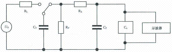
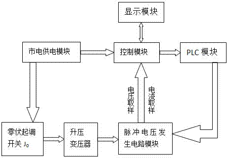
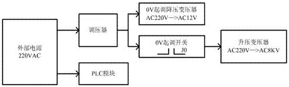
[0032] refer to figure 2 , discloses the capacitor pulse voltage test device, including a mains power supply circuit module for providing a power signal, a zero-volt start-up switch, a step-up transformer, a pulse voltage generation circuit module, a control module, a PLC module, and a display module; wherein , the mains power supply circuit is connected to the zero-volt starting switch in turn, and the step-up transformer is connected to the pulse voltage generating circuit module as its power input; the pulse voltage generating circuit module includes a plurality of AC contactors and generates current sampling signals and voltage sampling signals are input to the control module; the control module controls the initial working voltage, and provides initial input signals for the PLC m...
PUM
 Abstract
Description
Claims
Application Information