
Device and method for measuring divergence angle distribution of electron beam

A measuring device and a technology of divergence angle, which are applied in the field of electron beam parameter measurement to achieve the effect of high adjustment work efficiency

Active Publication Date: 2017-07-21
INST OF FLUID PHYSICS CHINA ACAD OF ENG PHYSICS
View PDF11 Cites 5 Cited by
  • Summary
  • Abstract
  • Description
  • Claims
  • Application Information

AI Technical Summary

Benefits of technology

The technical effect of this patented inventor's new type of apparatus called Electron Beam Diffraction Lens (EBLD) is described by its unique characteristics: 1) Its measurements are accurate because there is no need to guess how much they should beforehand, 2) By combining multiple different types of X ray sources into a single unit, high sensitivity can be achieved while maintaining good focus performance over wide angles, 3) Using chirp converging lenses instead of traditional reflection targets reduces noise interference from other signals, 4) Unlike existing methods like scanning laser diodes, EBFD allows for precise control of the scattering angle distribution, 5) A specialized instrument is provided at both ends of the device, allowing for simultanous detection of two wavelength components. Overall, these improvements improve the efficiency, ease of operation, and reliability of current techniques such as electron beam diffractive analysis.

Problems solved by technology

This technical problem addressed in this patents relates to measuring the characteristics (such as particle velocity) of electrons emitted during acceleration experiments with traditional techniques like laser scattering and atomic absorption). However, current measurements have drawbacks due to factors related to these technologies themselves and their precision. There may exist various sources of errors affecting the measured values, leading to poor performance evaluation and potential safety hazards. Therefore, new ways must be developed to improve upon existing methods used for accurate analysis of electronic beam properties.

Method used


Image

  • Device and method for measuring divergence angle distribution of electron beam
  • Device and method for measuring divergence angle distribution of electron beam
  • Device and method for measuring divergence angle distribution of electron beam

Examples


Embodiment 1

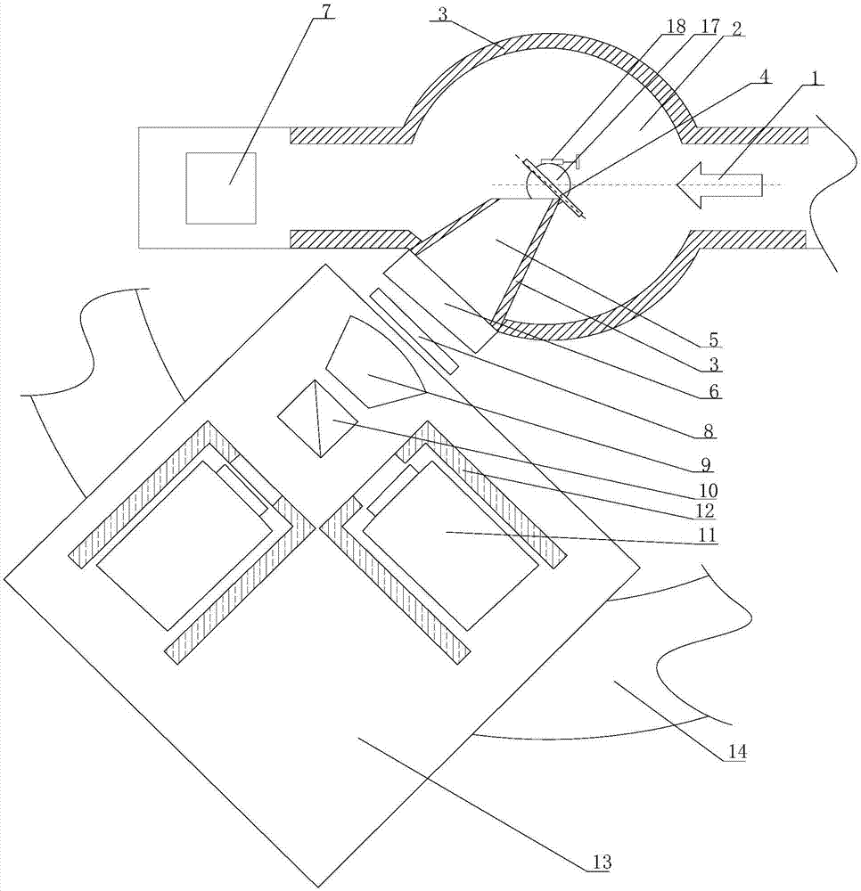
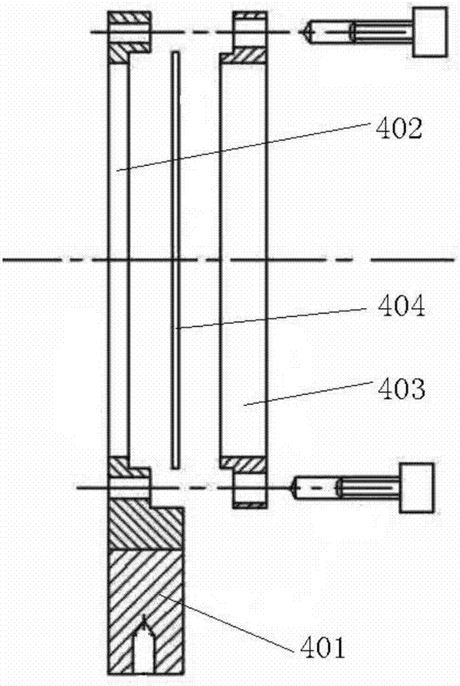
[0043] Such as figure 1 As shown, an electron beam divergence angle distribution measuring device of the present invention includes a sealed vacuum target chamber 2, and a conversion target 4 is installed in the sealed vacuum target chamber 2, and the electron beam 1 passing through the conversion target 4 will be placed behind The electron absorption graphite block 7 at the end absorbs, reduces the impact of the electron beam 1 on the vacuum target chamber and the measurement system, and reduces the radiation level of the measurement environment. The conversion target 4 is installed on a rotating optical bench 17, and also includes a rotating optical bench 17. There is a knob adjustment mechanism 18 for converting the position of the target 4 by the seat 17, and the azimuth of the conversion target 4 is adjusted to form a specific angle with the incident direction of the electron beam 1 through the provided knob adjustment mechanism 18, such as figure 2 The shown conversion ...

Embodiment 2

[0050] Such as figure 1 The principle shown in this embodiment is basically the same as that of Embodiment 1, and the only difference is: 1. image 3 The structure of the conversion target 4 shown is different. In this embodiment, the divergence angle of the electron beam is small, so the Mylar film should be selected. First, the rubber ring 413 is embedded in the ring groove in the target ring seat 415, and then there is no damage and scratches, etc. The defective film 414 is flattened on the surface of the target ring seat 415, and then the target ring pressure ring 411 is slowly pressed on the film, and the balance is maintained during the pressing process so that the film is pressed down evenly and the surface is kept flat. The process of pressing is also the process of stretching and tightening the film. After confirming that the stretching effect of the film meets the requirements, fasten the screw through the opening in the target ring pressure ring 411, which can maint...


PUM


Abstract

The invention discloses a device and method for measuring the divergence angle distribution of an electron beam, and the device comprises a sealed vacuum target room, a conversion target, and an anti-scattering shading column. The sealed vacuum target room is provided with a light output window corresponding to the anti-scattering shading column. The device also comprises an imaging system. After the electron beam bombards the conversion target, Cherenkov radiation light is generated, and the Cherenkov radiation light enters the anti-scattering shading column and then is outputted through the light output window. The Cherenkov radiation light is imaged on the imaging system after being filtered by a narrow band filter. According to the invention, after the electron beam bombards the conversion target, Cherenkov radiation light is generated, and the Cherenkov radiation light enters the anti-scattering shading column and then is outputted through the light output window. The focal plane imaging of the Cherenkov radiation light is carried out on the imaging system after being filtered by the narrow band filter. Through the focal plane imaging, the device deduces the divergence angle distribution of the electron beam by inversion.

Description


Claims


Application Information

Patent Timeline
Owner INST OF FLUID PHYSICS CHINA ACAD OF ENG PHYSICS
Learn More