Eureka AIR delivers breakthrough ideas for toughest innovation challenges, trusted by R&D personnel around the world.

Ac electric quantity measuring device

a technology of electric quantity measurement and measuring device, which is applied in the direction of power measurement by current/voltage, instruments, phase sequence/synchronization indication, etc., can solve the problems of large error, long computation time, and frequency measurement results obtained from equation (2) also contain certain errors, so as to improve the performance of an electric power system control/protection device, cost reduction

Active Publication Date: 2010-01-28
MITSUBISHI ELECTRIC CORP
View PDF10 Cites 16 Cited by
  • Summary
  • Abstract
  • Description
  • Claims
  • Application Information

AI Technical Summary

Benefits of technology

The present invention relates to an AC electric quantity measuring device that uses a real-time frequency measured in accordance with a dynamic frequency measuring method to calculate AC electric quantity with accuracy without any influence of harmonic or flickering (phase variation). The technical effect of the invention is to provide an improved AC electric quantity measuring device that can measure the frequency of an electric power system in real-time, allowing for quick and accurate AC electric quantity measurement.

Problems solved by technology

In either case, a long computation time is required or the result has a large error.
However, since phase variation due to voltage flickering or other produces errors in the voltage amplitude and the chord length, the frequency measurement result obtained from the equation (2) also contains a certain error.
Such a frequency measuring device cannot therefore measure the frequency in real time, which poses a problem in high-speed, high-accuracy AC electric quantity measurement.Patent Document 1: JP-A-2004-361124Patent Document 2: WO-PCT / JP2007 / 052967Non-Patent Document 1: “Development of Integral Method for Measuring RMS Active and Reactive Power in Single- and Multiphase Networks,” pp.

Method used

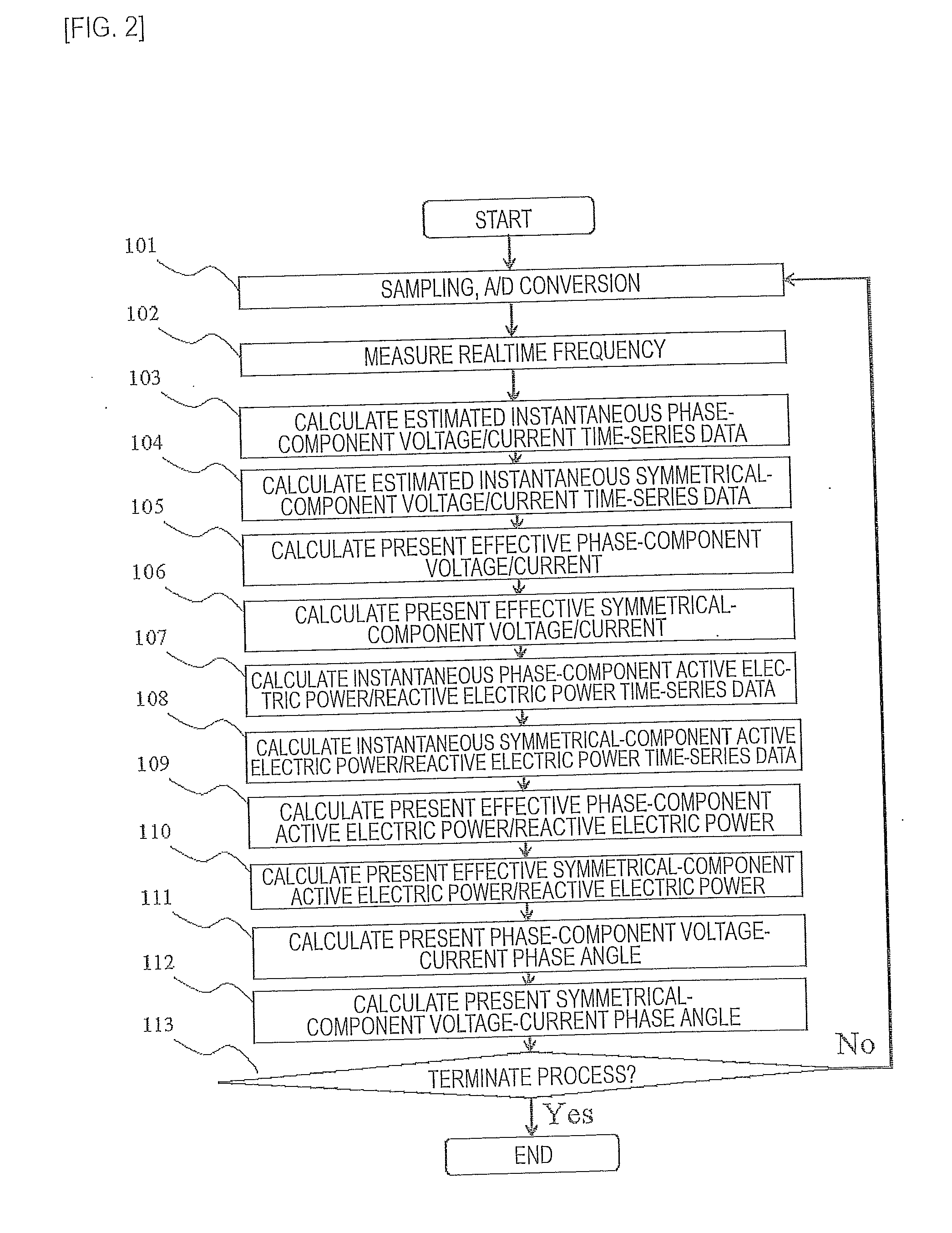

Image

  • Ac electric quantity measuring device
  • Ac electric quantity measuring device
  • Ac electric quantity measuring device

Examples


first embodiment

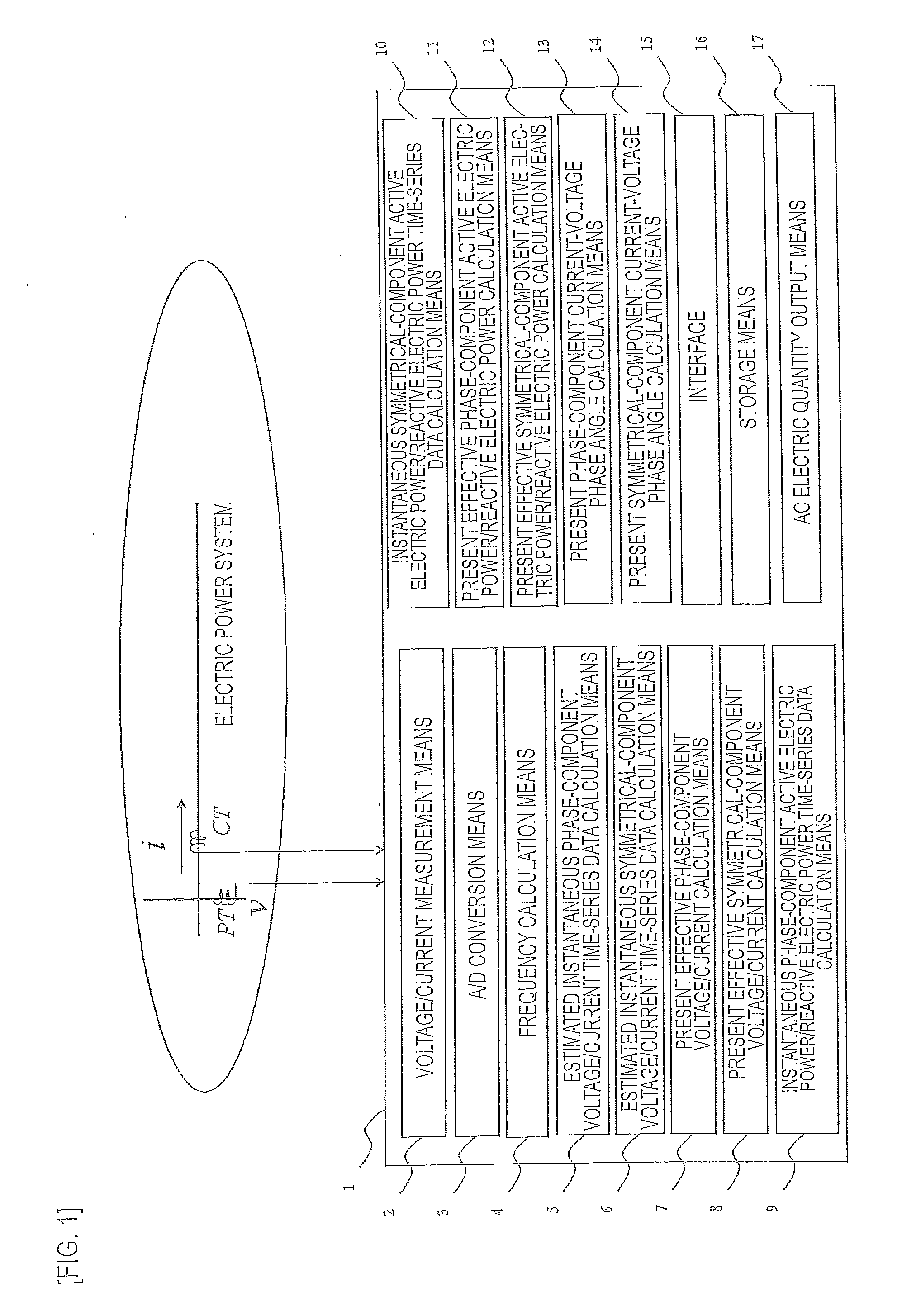
[0038]FIG. 1 is a configuration diagram of an AC electric quantity measuring device in an electric power system according to the invention. In FIG. 1, reference character PT denotes a voltage transformer for an instrument; reference character CT denotes a current transformer; reference character v denotes a voltage; and reference character i denotes a current. For the sake of simplicity, only the portion corresponding to a single phase is shown.

[0039]Reference numeral 1 denotes an AC electric quantity measuring device to which the invention is directed, and is comprised of a computer including a variety of functional means described below. That is, reference numeral 2 denotes voltage / current measurement means to which time-series data measured with PT and CT described above are inputted. Reference numeral 3 denotes A / C conversion means for converting the time-series analog data into time-series digital data. Reference numeral 4 denotes frequency calculation means for measuring the f...


PUM


Abstract

In the present invention, a measured realtime accurate frequency is used to determine estimated instantaneous voltage / current time-series data for each phase component in accordance with the least-squares method. The estimated instantaneous voltage / current time-series data are used to determine effective voltage, effective current, instantaneous active electric power, instantaneous reactive electric power, effective active electric power, and effective reactive electric power of each phase component and symmetrical component. The measured AC electric quantities are applied to any type of electric power system control / protection apparatus.

Description

TECHNICAL FIELD [0001]The present invention relates to an AC electric quantity measuring device using a realtime frequency and the least-squares method, the realtime frequency obtained in accordance with a dynamic frequency measuring method.BACKGROUND ART[0002]In recent years, as the flow in electric power systems becomes sophisticated, there has been a need to supply reliable, high-quality electric power. In particular, there has been an increasing need to improve the performance of an AC electric quantity measuring device in a three-phase circuit, a single-phase circuit, and an arbitrary multi-phase circuit that are essential in an electric power system control / protection device.[0003]The present inventor has already proposed that an approach based on a rotation vector on a complex plane is useful to improve the performance in controlling and protecting an electric power system. This proposal is based on a basic approach in which AC voltage and current are expressed as vectors tha...

Claims


Application Information

Patent Timeline
Patent Type & Authority Applications(United States)
IPC IPC(8): G01R21/06
CPCG01R29/18G01R19/2513
Inventor SEKI, KEMPEI
Owner MITSUBISHI ELECTRIC CORP
Why Eureka
Eureka Blog
Learn More