Method of Measuring a Structure, Inspection Apparatus, Lithographic System, Device Manufacturing Method and Wavelength-Selective Filter for Use therein

a technology of wavelengths and filters, applied in the field of metrology, can solve the problems of affecting the accuracy of measurement results, and the time penalty for measuring two different wavelengths is greater per target, so as to reduce the influence of process variations and improve accuracy

Active Publication Date: 2017-08-24
ASML NETHERLANDS BV
View PDF2 Cites 17 Cited by
  • Summary
  • Abstract
  • Description
  • Claims
  • Application Information

AI Technical Summary

Benefits of technology

[0010]The inventors have devised a simple modification of the illumination and detection system, which will allow measurements to be made simultaneously at two wavelengths, with accuracy similar to that of the known measurements. The invention can be applied in angle-resolved scatterometry generally, whether by detection in the pupil plane or by dark-field imaging. Accuracy can be improved over prior published techniques by reducing the influence of process variations.

Problems solved by technology

As will be appreciated, however, measurements using two different wavelengths will incur a greater time penalty per target.

Method used


Image

  • Method of Measuring a Structure, Inspection Apparatus, Lithographic System, Device Manufacturing Method and Wavelength-Selective Filter for Use therein
  • Method of Measuring a Structure, Inspection Apparatus, Lithographic System, Device Manufacturing Method and Wavelength-Selective Filter for Use therein
  • Method of Measuring a Structure, Inspection Apparatus, Lithographic System, Device Manufacturing Method and Wavelength-Selective Filter for Use therein

Examples


application example

Dual-Wavelength Capture—Application Example

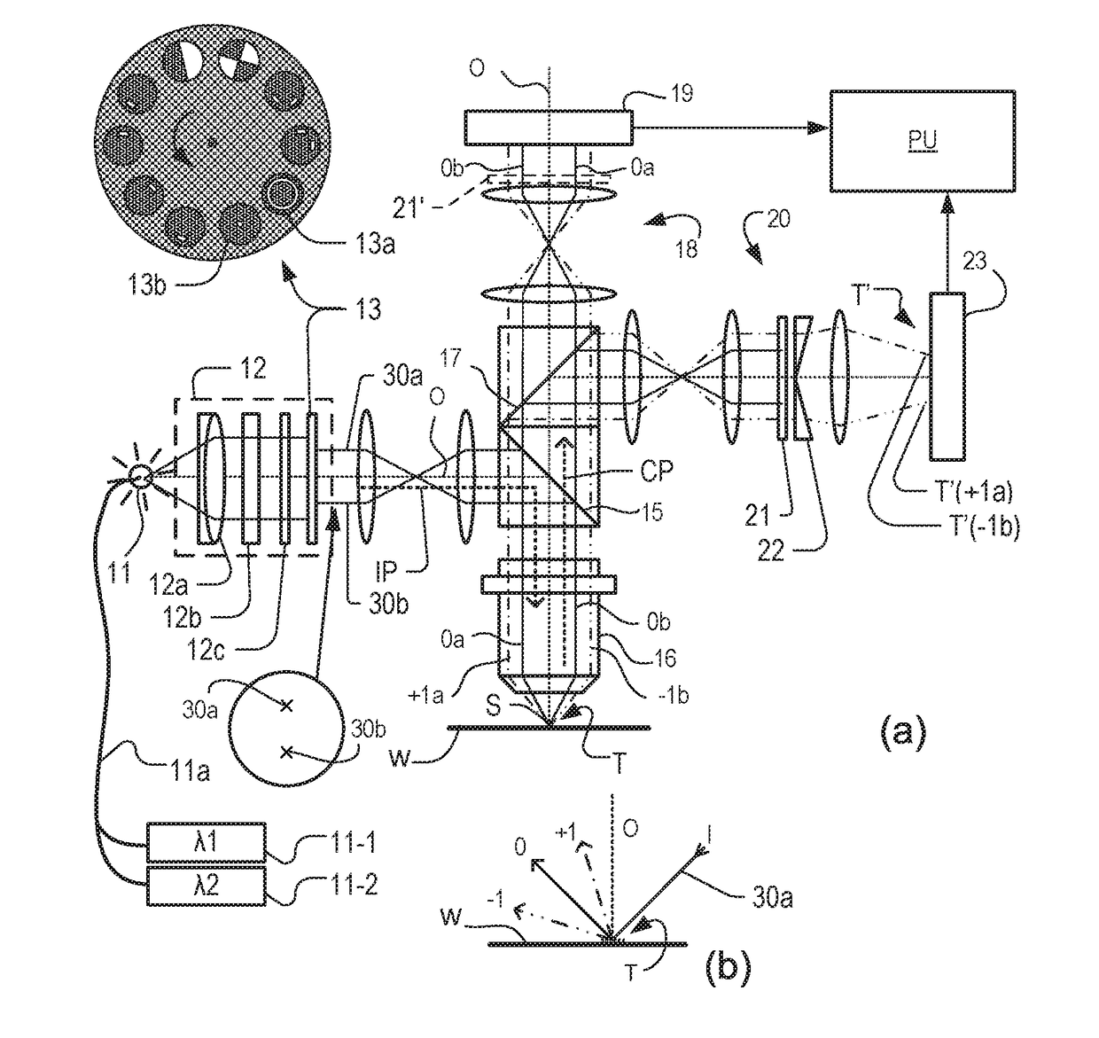
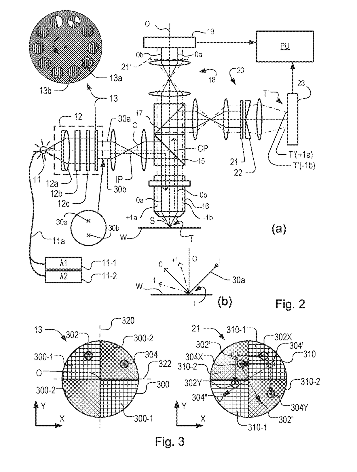
[0086]An application will now be described, beginning with a description of the principle of the existing small target diffraction-based overlay methods, mentioned in the introduction. The dual-wavelength capture principle is not limited to this particular application, and is not limited to dark-field imaging metrology generally. A second filter 310 can be deployed equally in the first measurement branch, using pupil image sensor 19, as indicated in dotted lines at 21′.

[0087]FIG. 6 depicts a composite target formed on a substrate W according to known practice. The composite target comprises four periodic structures in the form of gratings 62 to 65 positioned closely together so that they will all be within the measurement spot S formed by the illumination beam of the metrology apparatus. A circle 61 indicates the extent of spot S on the substrate W. The four gratings thus are all simultaneously illuminated and simultaneously imaged on senso...


PUM

PropertyMeasurementUnit
wavelengthsaaaaaaaaaa

Abstract

A scatterometer performs diffraction based measurements of one or more parameters of a target structure. To make two-color measurements in parallel, the structure is illuminated simultaneously with first radiation (302) having a first wavelength and a first angular distribution and with second radiation (304) having a second wavelength and a second angular distribution. The collection path (CP) includes a segmented wavelength-selective filter (21, 310) arranged to transmit wanted higher order portions of the diffracted first radiation (302X, 302Y) and of the diffracted second radiation (304X, 304Y), while simultaneously blocking zero order portions (302″, 304″) of both the first radiation and second radiation. The illumination path (IP) in one embodiment includes a matching segmented wavelength-selective filter (13, 300), oriented such that a zero order ray passing through the illumination optical system and the collection optical system will be blocked by one of said filters or the other, depending on its wavelength.

Description

BACKGROUND[0001]Field of the Invention[0002]The present invention relates to methods and apparatus for metrology usable, for example, in the manufacture of devices by lithographic techniques and to methods of manufacturing devices using lithographic techniques. The invention relates in particular to methods and apparatuses for measuring a property of a structure formed by a lithographic process on a substrate.[0003]Background Art[0004]A lithographic apparatus is a machine that applies a desired pattern onto a substrate, usually onto a target portion of the substrate. A lithographic apparatus can be used, for example, in the manufacture of integrated circuits (ICs). In that instance, a patterning device, which is alternatively referred to as a mask or a reticle, may be used to generate a circuit pattern to be formed on an individual layer of the IC. This pattern can be transferred onto a target portion (e.g., including part of, one, or several dies) on a substrate (e.g., a silicon wa...

Claims


Application Information

Patent Timeline
Patent Type & Authority Applications(United States)
IPC IPC(8): G03F7/20G02B5/22G01N21/47
CPCG03F7/70191G03F7/70133G01N2021/4711G02B5/22G01N2201/063G01N21/4788G03F7/70616G03F7/70625
Inventor PANDEY, NITESHDEN BOEF, ARIE JEFFREYVAN DAM, MARINUS JOHANNES MARIA
Owner ASML NETHERLANDS BV
Why Eureka
Try Eureka