A method and device for establishing a nested grid

A technology for establishing methods and grid positions, applied in instrumentation, geometric CAD, calculation, etc., can solve problems such as complex methods, inapplicability to main components, and difficulty in obtaining component flow field transfer data.

Active Publication Date: 2019-03-01
BEIJING AERONAUTIC SCI & TECH RES INST OF COMAC +1
View PDF3 Cites 0 Cited by
  • Summary
  • Abstract
  • Description
  • Claims
  • Application Information

AI Technical Summary

Problems solved by technology

[0004] The disadvantages of the above nested structured grid technology are: the method of identifying the nesting relationship between the grids of different components is complicated, it is not easy to obtain the flow field transfer data between components, and it is not suitable for assemblies without a clear main component

Method used


Image

  • A method and device for establishing a nested grid
  • A method and device for establishing a nested grid
  • A method and device for establishing a nested grid

Examples


Embodiment 1

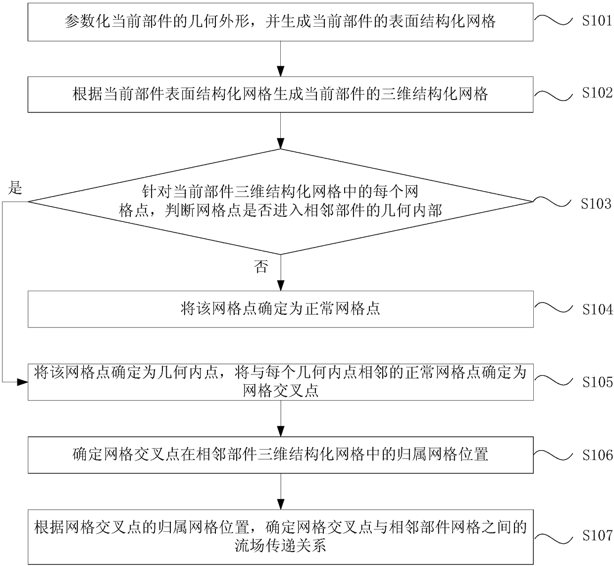
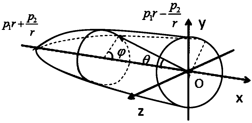
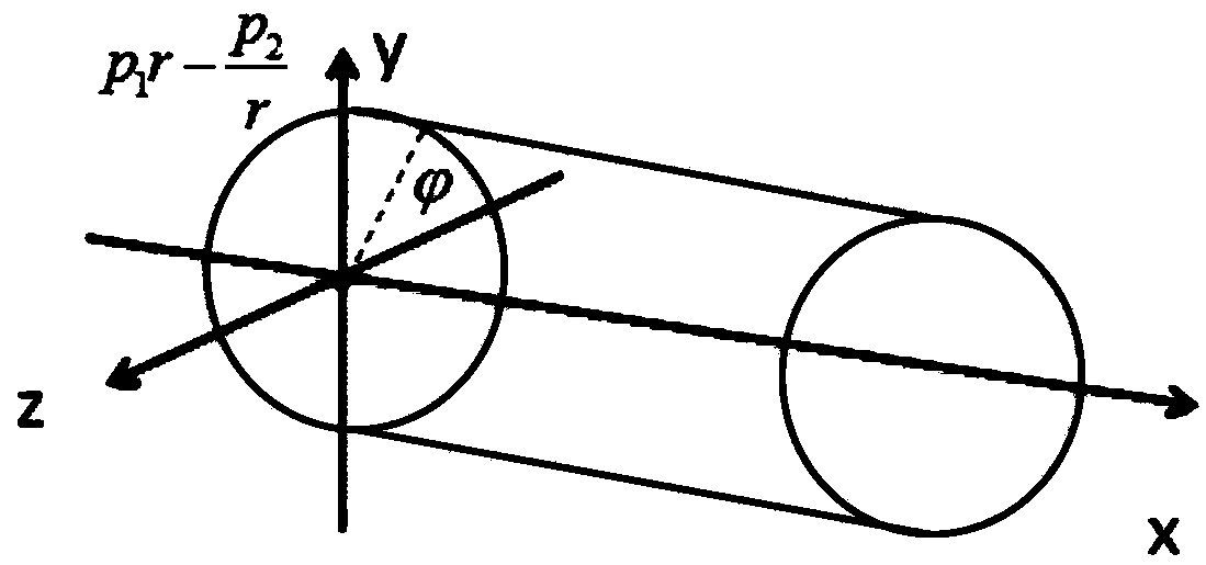
[0038] figure 1 It is a flowchart of a method for establishing a nested grid provided in Embodiment 1 of the present invention, Figure 2a is the ellipsoid coordinate system generated by the structured grid of the front section of the three-dimensional fuselage in the nested grid establishment method provided by Embodiment 1 of the present invention, Figure 2b is the cylindrical coordinate system generated by the structured grid of the rear section of the three-dimensional fuselage in the nested grid establishment method provided by Embodiment 1 of the present invention, Figure 3a is the physical domain of the conformal transformation method used to generate the wing structured grid in the nested grid establishment method provided by Embodiment 1 of the present invention, Figure 3b is the reference domain of the conformal transformation method used for generating the wing structured grid in the nested grid establishment method provided by Embodiment 1 of the present invent...

Embodiment 2

[0064] Figure 4 It is a flowchart of a method for establishing a nested grid provided in Embodiment 2 of the present invention, Figure 5 It is a schematic diagram of the method for identifying points entering the geometry of fuselage components in the nested grid establishment method provided by Embodiment 2 of the present invention. Embodiment 2 is based on the above-mentioned embodiment. Preferably, for each grid point in the three-dimensional structured grid of the current component, it is determined whether the grid point enters the geometric interior of the adjacent component, and is optimized to determine whether the grid point is Within the range of the cuboid marked by the minimum and maximum values ​​of the three coordinate directions of the three-dimensional structured grid of the adjacent component; if it is within the range of the cuboid, locate the corresponding adjacent component y-z section according to the x coordinate of the grid point; Calculate the angle ...

Embodiment 3

[0081] Figure 6 It is a flowchart of a method for establishing a nested grid provided in Embodiment 3 of the present invention, Figure 7 It is a schematic diagram of the method for identifying points entering the geometric interior of the wing component in the nested grid establishment method provided by the third embodiment of the present invention. The third embodiment is based on the above-mentioned embodiments. Preferably, for each grid point in the three-dimensional structured grid of the current component, it is determined whether the grid point enters the geometric interior of the adjacent component, and is optimized to determine whether the grid point is Within the range of the cuboid marked by the minimum and maximum values ​​of the three coordinate directions of the three-dimensional structured grid of the adjacent component; if it is within the range of the cuboid, determine the first projection point of the grid point on the geometric upper surface of the adjacen...


PUM


Abstract

The embodiment of the invention discloses a method and a device for establishing a nested grid. The method comprises the following steps that: generating the surface structured grid of a current component; generating the three-dimensional structured grid of the current component; judging whether a grid point enters the geometric inner side of an adjacent component or not; if the grid point enters the geometric inner side of the adjacent component, determining the grid point as a geometric inner point, and otherwise, determining the grid point as a normal grid point; determining a normal grid point adjacent to each geometric inner point as a grid cross point; determining a current component far-field boundary point cross with the adjacent component grid as a grid cross point; determining the affiliation grid point of the grid cross point in the three-dimensional structured grid of the adjacent component; and according to the affiliation grid point of the grid cross point, determining a flow field transferring relationship between the grid cross point and the adjacent component grid. By use of the embodiment of the invention, a nesting relationship among different component grids can be quickly and conveniently screened, the flow field transferring relationship between the grid cross point and the adjacent component grid can be accurately and effectively determined, and an airplane configuration flow field information transferring way formed by any fuselage wing component can be analyzed.

Description

technical field [0001] Embodiments of the present invention relate to aerodynamic design technology, and in particular to a method and device for utilizing nested grids. Background technique [0002] For the overall aerodynamic design of the aircraft, a basic element is the rapid and accurate analysis of the flow field characteristics of various configurations of the aircraft. With the continuous development of computational fluid dynamics (Computational FluidDynamics, CFD) technology, many commercially mature software has been widely used in the engineering practice of aircraft design, but most of the software needs to be read in by a third-party network before the flow field analysis. However, it often takes a long time to build a set of high-quality grids. [0003] At present, there is a kind of nested structured grid technology that generates corresponding body-fitted orthogonal grids according to the geometric characteristics of each model. Among them, the grid of the...

Claims


Application Information

Patent Timeline
Patent Type & Authority Patents(China)
IPC IPC(8): G06F17/50
CPCG06F30/15G06F30/20
Inventor 孙明哲
Owner BEIJING AERONAUTIC SCI & TECH RES INST OF COMAC
Why Eureka
Try Eureka