
A pcb split board mobile handling mechanism
A technology of handling mechanism and board separation, applied in the direction of conveyor objects, transportation and packaging, electrical components, etc., can solve the problems of affecting the yield, low efficiency, poor effect, etc., and achieve good effect and high efficiency
- Summary
- Abstract
- Description
- Claims
- Application Information
AI Technical Summary
Problems solved by technology
Method used
Image

Examples
Embodiment Construction
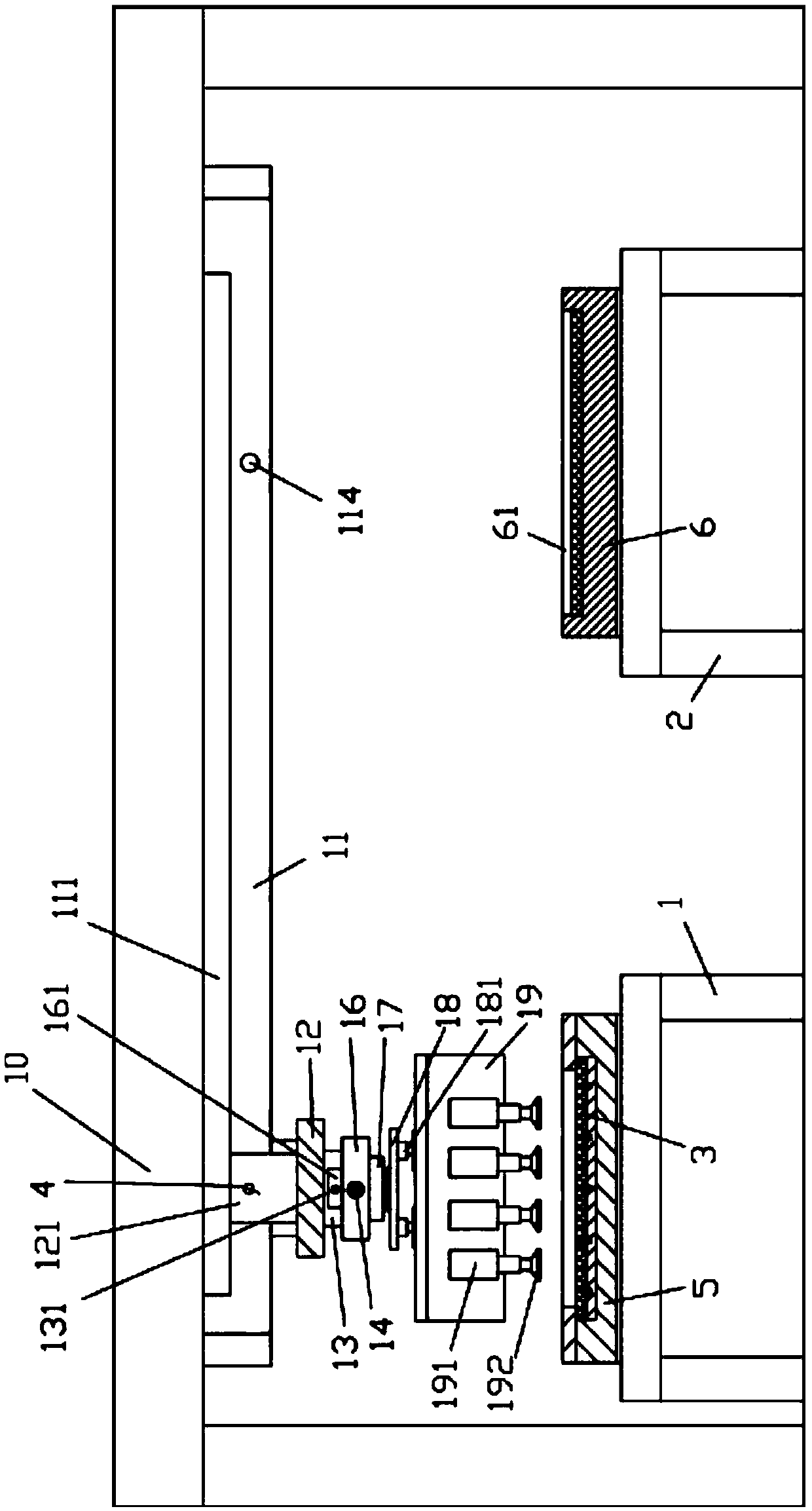
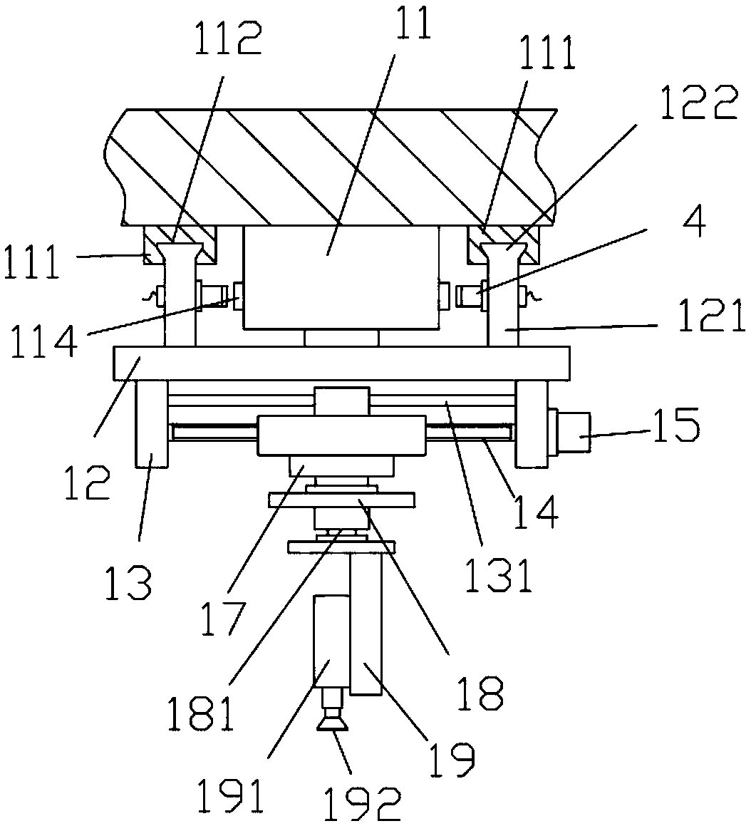
[0018] Examples, see e.g. Figure 1 to Figure 2 As shown, a PCB sub-board mobile handling mechanism includes a handling frame 10, a PCB placement frame 1 and a shelf to be placed 2, and the PCB placement frame 1 and the shelf to be placed 2 are all below the top plate of the handling frame 10;
[0019] The bottom surface of the top plate of the carrier frame 10 is fixed with a horizontal rodless cylinder 11, the push block of the horizontal rodless cylinder 11 is fixed with a connecting plate 12, the front and rear ends of the connecting plate 12 are fixed with a support plate 13, and the drive screw 14 is fixed on the bottom surface of the connecting plate 12. The two ends are hinged on two support plates 13, wherein a drive motor 15 is fixed on the outer wall of one support plate 13, the output shaft of the drive motor 15 is a spline shaft, and the spline shaft is sleeved on one end of the transmission screw rod 14. In the spline hole, the moving block 16 is screwed in the t...
PUM
 Abstract
Description
Claims
Application Information