Sealing method for cylindrical battery

A cylindrical battery and sealing technology, which is applied in the manufacture of primary batteries, cylindrical shell batteries/batteries, secondary batteries, etc., can solve problems such as low efficiency, high sealing edge, and no sealing size design method, so as to improve battery performance, Improve the design capacity and improve the effect of battery liquid retention capacity

Inactive Publication Date: 2017-07-21
SHENZHEN ANDING NEW ENERGY TECH DEV CO LTD
View PDF0 Cites 6 Cited by
  • Summary
  • Abstract
  • Description
  • Claims
  • Application Information

AI Technical Summary

Problems solved by technology

[0005] The sealing size of a cylindrical battery is affected by the thickness of the steel shell, the specification of the sealing mold, the thickness of the cap busbar, the thickness of the upper and lower rubber rings of the cap, and the compression rate of the rubber ring; currently there is no reasonable design method for the sealing size. Debug the sealing mold for the first time, the height of the sealing edge, repeatedly verify the airtightness of the sealing, the breaking pressure and opening pressure of the sealing cap; until a reasonable sealing size is tested
This verification method is inefficient and wastes manpower and material resources.

Method used


Image

  • Sealing method for cylindrical battery
  • Sealing method for cylindrical battery
  • Sealing method for cylindrical battery

Examples


Embodiment 1

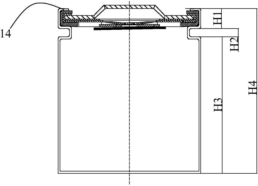
[0039] For a 32650 cylindrical battery, the wall thickness M of the steel case 10 is 0.5mm, the chamfering height h of the sealing mold 40 is 0.2mm, and the thickness L1 of the upper rubber ring part 372 is 0.7mm; The distance K is 1.75mm; the thickness L2 of the lower rubber ring part 373 is 0.7mm; the compression rate of the upper rubber ring part 372 and the lower rubber ring part 373 is 50%; adopt the sealing method of the present invention, the second bottom wall 131 and the described The distance H1 between the two opposite surfaces of the inner edge 14 = 2×0.5+0.2+0.7×(1-50%)+1.75+0.7×(1-50%)=3.65mm.

[0040] The thickness N of the hob 20 is 1.5 mm, and the distance H2 between the opposite surfaces of the second bottom wall 131 and the third bottom wall 132 of the groove 13 is equal to the thickness N of the hob, which is 1.5 mm.

[0041] The distance from the surface of the first bottom wall 11 opposite to the inner edge 14 to the surface of the third bottom wall 132 o...

Embodiment 2

[0043] For a 32650 cylindrical battery, the wall thickness M of the steel case 10 is 0.5mm, the chamfering height h of the sealing mold 40 is 0.2mm, and the thickness L1 of the upper rubber ring part 372 is 0.7mm; The distance K is 1.75mm; the thickness L2 of the lower rubber ring part 373 is 0.7mm; the compression rate of the upper rubber ring part 372 and the lower rubber ring part 373 is 70%; adopt the sealing method of the present invention, the second bottom wall 131 and the described The distance H1 between the two opposite surfaces of the inner edge 14 = 2×0.5+0.2+0.7×(1-70%)+1.75+0.7×(1-70%)=3.37mm.

[0044] The thickness N of the hob 20 is 1.5 mm, and the distance H2 between the opposite surfaces of the second bottom wall 131 and the third bottom wall 132 of the groove 13 is equal to the thickness N of the hob, which is 1.5 mm.

[0045] The distance from the surface of the first bottom wall 11 opposite to the inner edge 14 to the surface of the third bottom wall 132 o...

Embodiment 3

[0047] For a 32650 cylindrical battery, the wall thickness M of the steel case 10 is 0.5mm, the chamfering height h of the sealing mold 40 is 0.2mm, and the thickness L1 of the upper rubber ring part 372 is 0.7mm; The distance K is 1.75mm; the thickness L2 of the lower rubber ring part 373 is 0.7mm; the compression rate of the upper rubber ring part 372 and the lower rubber ring part 373 is 70%; adopt the sealing method of the present invention, the second bottom wall 131 and the described The distance H1 between the two opposite surfaces of the inner edge 14 = 2×0.5+0.2+0.7×(1-70%)+1.75+0.7×(1-70%)=3.37mm.

[0048] The thickness N of the hob 20 is 1.2 mm, and the distance H2 between the opposite surfaces of the second bottom wall 131 and the third bottom wall 132 of the groove 13 is equal to the thickness N of the hob, which is 1.2 mm.

[0049] The distance from the surface of the first bottom wall 11 opposite to the inner edge 14 to the surface of the third bottom wall 132 o...


PUM


Abstract

The invention discloses a sealing method for a cylindrical battery. The method includes the following steps that 1, a steel housing provided with a first bottom wall and a side wall, a hobbing cutter, a cover cap and a seal mold, wherein the thickness of the steel housing is M, the thickness of the hobbing cutter is N, the cover cap includes an upper rubber ring part and a lower rubber ring part, the thickness of the upper rubber ring part is L1, the thickness of the lower rubber ring part is L2, the seal mold includes a circular arc chamfering, and the height of the seal mold is h; 2, a groove is formed in the steel housing through the hobbing cutter by pressing, wherein the groove includes a second bottom wall and a third bottom wall; 3, the cover cap is placed in the steel housing; 4, an inner edge is formed by pressing the side wall with the seal mold. The distance between the surfaces, opposite to each other, of the upper rubber ring part and the lower rubber ring part is K, and the distance between the two surfaces, opposite to the inner edge, of the second bottom wall is H1, wherein H1=2M+h+L1(1-X)+K+L2*(1-X), the compression ratio of the upper rubber ring part is X and the compression ratio of the lower rubber ring part is X. The distance H2 between the surfaces, opposite to each other, of the second bottom wall and the third bottom wall of the groove can be adjusted through the thickness N of the hobbing cutter; the distance between the surface, opposite to the inner edge, of the first bottom wall and the surface, opposite to the first bottom wall, of the third bottom wall is H3, wherein H3=H4-H1-H2.

Description

[0001] 【Technical field】 [0002] The invention relates to the field of power batteries, in particular to a cylindrical battery sealing method. [0003] 【Background technique】 [0004] With the increasingly severe energy and environmental problems, the country's strong support for new energy, and the increasingly mature key technologies of power batteries, power batteries have been widely used in electric cars, electric motorcycles, electric bicycles, solar energy, mobile communication terminal products and energy storage and other products. Cylindrical steel case batteries are mechanically extruded on the outer wall of the steel case, and the sealing rubber ring of the compressed cap is deformed to a certain extent to achieve a sealing effect. [0005] The sealing size of a cylindrical battery is affected by the thickness of the steel shell, the specification of the sealing mold, the thickness of the cap busbar, the thickness of the upper and lower rubber rings of the cap, an...

Claims


Application Information

Patent Timeline
Patent Type & Authority Applications(China)
IPC IPC(8): H01M10/04H01M6/00
CPCH01M6/00H01M10/0422Y02E60/10Y02P70/50
Inventor 邓昌源刘家捷边颖许辉
Owner SHENZHEN ANDING NEW ENERGY TECH DEV CO LTD
Why Eureka
Try Eureka