
Method for multi-dimensional joint estimation of dynamic sparse channels under MIMO system

A multi-dimensional joint, sparse channel technology, applied in the field of multi-dimensional joint estimation of dynamic sparse channels under MIMO systems, can solve problems such as reducing spectrum utilization, affecting channel estimation accuracy, and increasing channel coefficients

Active Publication Date: 2017-07-21
SHANGHAI JIAO TONG UNIV
View PDF5 Cites 7 Cited by
  • Summary
  • Abstract
  • Description
  • Claims
  • Application Information

AI Technical Summary

Problems solved by technology

[0004] But for the dynamic sparse channel under the MIMO system, on the one hand, the transmitting end and the receiving end have multiple antennas, and the channel coefficients to be estimated are greatly increased, which means that more pilot subcarriers are needed, and the pilot overhead increases. , which reduces the spectrum utilization; on the other hand, the delay characteristics of the dynamic channel will change dynamically with time, and the channel taps with non-zero gain may appear or disappear at a certain moment, resulting in the change of the channel sparsity
The previously proposed channel estimation schemes based on CS and DCS ignore this dynamic change, and take the channel sparsity as a fixed value, which will seriously affect the accuracy of channel estimation.

Method used


Image

  • Method for multi-dimensional joint estimation of dynamic sparse channels under MIMO system
  • Method for multi-dimensional joint estimation of dynamic sparse channels under MIMO system
  • Method for multi-dimensional joint estimation of dynamic sparse channels under MIMO system

Examples


Embodiment Construction

[0046] The present invention will be further described below in conjunction with the accompanying drawings and specific embodiments. This implementation is intended to be carried out on the premise of the technical solution of the present invention, and detailed implementation methods and specific operation processes are given, but the protection scope of the present invention is not limited to the following examples.

[0047] LTE is a wireless communication protocol based on OFDM transmission system. When using 30MHz bandwidth for downlink wireless communication according to the LTE protocol, the CE-BEM order Q=3, the number of channel paths L=32, the number of subcarriers N=2048, the number of pilots G=90, and the number of base station transmitting antennas N t =12, the number of OFDM symbols sent J=10, the channel sparsity K at the initial moment (1) =5. The specific steps of multi-dimensional joint estimation of dynamic sparse channel under a MIMO system of the present ...


PUM


Abstract

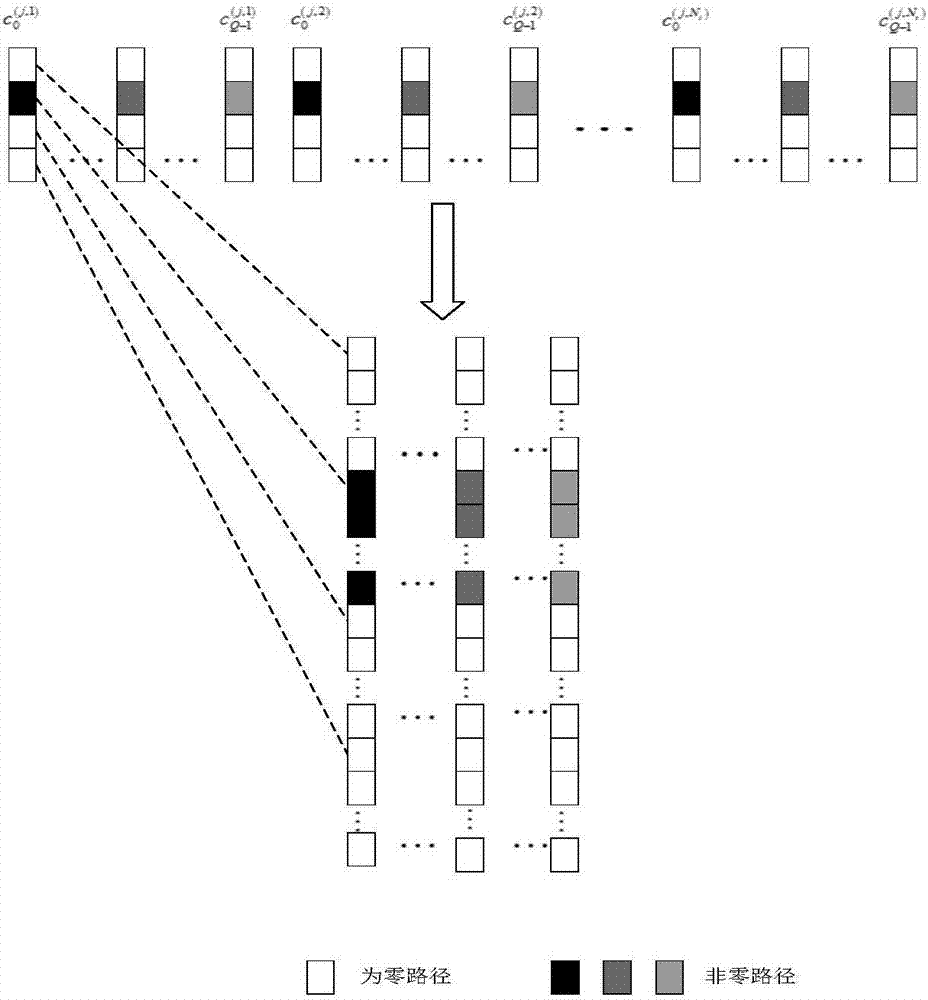
The invention discloses a method for multi-dimensional joint estimation of dynamic sparse channels under an MIMO system. The method comprises the following steps: (1) modeling a time-frequency doubly selective channel by using a complex exponential basis expansion model; (2) ensuring that BEM coefficients of different antennae and different orders have joint sparsity, and re-arranging basis expansion model coefficients by using the block sparsity to form a block structure; (3) adopting a hierarchical pilot design for multi-antenna scenarios, distributing pilot locations in N sub-carriers with equal intervals, and deducing a channel estimation model; (4), determining the channel sparsity K (j) at the moments corresponding to different OFDM symbols according to the time correlation of the dynamic sparse channels, wherein j is equal to 1, 2, ..., J; (5) reconstructing to obtain a sparse coefficient FORMULA according to the determined sparsity corresponding to each moment; and (6) recovering a channel tap coefficient FORMULA from the sparse coefficient. By adopting the method disclosed by the invention, the dynamic features of the sparse channels can be effectively estimated, the channel characteristics of the dynamic sparse channels can be obtained, and the accuracy of channel estimation and the spectrum utilization can be increased.

Description

Technical field: [0001] The present invention relates to a method for channel estimation by a receiver when a base station and a mobile terminal perform uplink and downlink communication in a time-frequency dual selective fading environment, specifically a method for multi-dimensional joint estimation of a dynamic sparse channel under a MIMO system, belonging to The field of wireless communication technology. Background technique: [0002] In a wireless communication system, in order to effectively restore the original transmitted signal, the receiver needs to estimate the channel state information, and then perform equalization processing on the received signal. Therefore, the accuracy of channel estimation is crucial to the performance of wireless communication systems. [0003] Based on the sparsity of the channel, more and more studies use Compressed Sensing (CS) theory for sparse channel estimation. The CS theory breaks through the limitation of the Nyquist sampling th...

Claims


Application Information

Patent Timeline
IPC IPC(8): H04B7/0413H04L25/02H04B17/391
CPCH04B7/0413H04L25/024H04B17/391
Inventor 张弦归琳宫博秦启波
Owner SHANGHAI JIAO TONG UNIV
Learn More