
Mini-tiller with mowing function

A micro-tiller and functional technology, applied in the field of micro-tillers, can solve the problems of energy loss, difficulty in operation, insufficient power, etc., and achieve the effects of reducing energy loss, prolonging battery life and convenient operation.

Inactive Publication Date: 2017-07-25
耒阳市丰收蔡伦机械有限公司
View PDF0 Cites 6 Cited by
  • Summary
  • Abstract
  • Description
  • Claims
  • Application Information

AI Technical Summary

Problems solved by technology

At present, the miniature tillage machines sold on the market and used by farmers need to clean up the abandoned plants before tilling in weeds or uncleared crop fields, otherwise it is easy to cause the plants to get stuck and the rolling wheels of the tiller cannot be used. operation, or difficulty in operation; although there are micro-tillers with mowing functions in the prior art, the mowing mechanisms on them are all driven by electric motors, so power shortages often occur, and electric drives require diesel engines or gasoline engine for power generation, the conversion between energy sources will cause a large amount of energy loss, which not only increases the operating cost of the tiller, but also affects the battery life of the tiller; in addition, the mowing mechanism is exposed at the front end of the tiller, not only Highly dangerous and messy grass is not easy to be cut at one time, which greatly affects the effect of mowing

Method used


Image

  • Mini-tiller with mowing function
  • Mini-tiller with mowing function
  • Mini-tiller with mowing function

Examples


Embodiment Construction

[0017] The following will clearly and completely describe the technical solutions in the embodiments of the present invention with reference to the accompanying drawings in the embodiments of the present invention. Obviously, the described embodiments are only some, not all, embodiments of the present invention. Based on the embodiments of the present invention, all other embodiments obtained by persons of ordinary skill in the art without making creative efforts belong to the protection scope of the present invention.

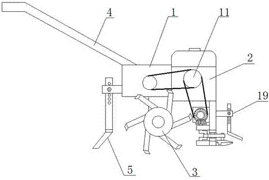
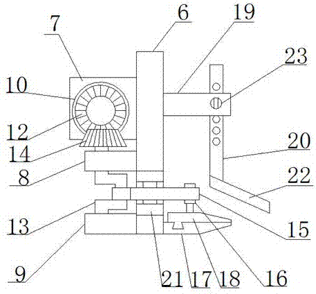
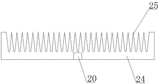
[0018] refer to Figure 1-3 , a micro tillage machine with a mowing function, comprising a body 1, a machine head 2 connected to the front end of the body 1, a tillage mechanism 3 connected to the lower end of the body 1, a steering control mechanism 4 connected to the rear end of the body 1, and a The booster mechanism 5 on the rear side of the cultivating mechanism 3, the lower end of the head 2 is connected with a mowing mechanism.

[0019] The mowing mech...


PUM


Abstract

The invention discloses a micro tillage machine with a mowing function, which comprises a machine head connected to the front end of the machine body. Rod, the rear end of the first vertical rod is connected with the first mounting plate, the second mounting plate and the third mounting plate, one side of the first mounting plate is connected to the first belt pulley in rotation, and the first belt pulley is connected with the first belt pulley on the machine head. The two belt pulleys are connected in transmission, the first pulley is coaxially connected with the first helical gear, the crankshaft is vertically arranged between the second mounting plate and the third mounting plate, the lower end of the crankshaft is rotationally connected with the third mounting plate, and the upper end of the crankshaft The second helical gear is connected, the crank arm of the crankshaft is rotatably connected with a transmission rod, the middle part of the transmission rod is rotatably connected with the first vertical rod through the rotating part, and the other end of the transmission rod is movably connected with the second vertical rod. The invention can not only reduce energy consumption, prolong the service life of the tiller, but also improve the mowing effect.

Description

technical field [0001] The invention relates to a micro tillage machine, in particular to a micro tillage machine with the function of mowing grass. Background technique [0002] Tillers are powered by small diesel engines or gasoline engines, and have the characteristics of light weight, small size, and simple structure. Tillers are widely used in dry land, paddy fields, orchards, etc. in plains, mountains, and hills. The tiller can be used freely in the field, which is convenient for users to use and store. It saves the trouble that large-scale agricultural machinery cannot enter the fields in mountainous areas. It is the best choice for farmers and consumers to replace cattle farming. At present, the miniature tillage machines sold on the market and used by farmers need to clean up the abandoned plants before tilling in weeds or uncleared crop fields, otherwise it is easy to cause the plants to get stuck and the rolling wheels of the tiller cannot be used. operation, or...

Claims


Application Information

Patent Timeline
IPC IPC(8): A01D43/12
CPCA01D43/12
Inventor 段和平刘湘慧
Owner 耒阳市丰收蔡伦机械有限公司
Learn More