Vacuum high speed blender

A vacuum wall breaker and vacuum nozzle technology, which is applied to household appliances, applications, kitchen appliances, etc., can solve the problems of high vacuum pressure, affecting appearance, easy damage or loss of silicone valves, etc., to avoid loss or damage, assembly operations Convenience and improved service life

Active Publication Date: 2017-07-25
中山市索虹电器实业有限公司
View PDF11 Cites 30 Cited by
  • Summary
  • Abstract
  • Description
  • Claims
  • Application Information

AI Technical Summary

Problems solved by technology

[0003] During the use of the wall breaker, the cup lid is likely to be directly splashed with food residues. Users usually wash the cup lid, vacuum nozzle and other components. At this time, it is inevitable that there will be water remaining on the cup lid, vacuum nozzle and other components. Above, the residual water will seriously affect the life of the air pump
[0004] In order to return air to the cup body, a vent valve is usually provided on the cup cover. The conventional vent valve includes a vent hole on the cup cover and a silicone valve that can be plugged into the vent hole. When venting, just put the silicone valve Just pull it out, but the vacuum pressure of the cup is likely to be high, and the silicone valve is easily damaged or lost after being pulled out many times, and it will affect the appearance of the cup
[0005] In addition, the lid is provided with vent holes and the vent holes are respectively connected to the outside world, which also leads to a more complicated structure of the cup lid and affects the appearance.

Method used


Image

  • Vacuum high speed blender
  • Vacuum high speed blender
  • Vacuum high speed blender

Examples


Embodiment Construction

[0042] The present invention will be further described below in conjunction with the accompanying drawings and embodiments.

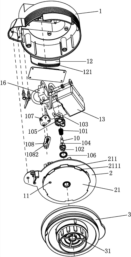
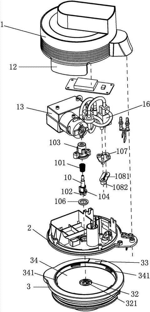
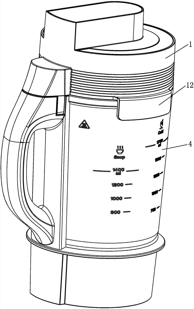
[0043] see Figure 1-Figure 16 , this vacuum breaker, comprises the main cover that is made of cup cover 1 and bottom cover 2, is provided with the suction suction nozzle 10 that forms vacuum circuit, vacuum assembly and exhaust hole 11 on it, is characterized in that, also It includes a sub-cover 3 used to cover the cup body 4 of the broken wall machine. The sub-cover 3 is provided with a vacuum nozzle 32, and the bottom cover 2 and the sub-cover 3 are detachable and assembled by a positive and negative twist buckle mechanism;

[0044] The suction nozzle 10 moves up and down on the bottom cover 2 through the elastic device, the suction nozzle 10 is provided with an upper coupling part 102, and the vacuum nozzle 32 is provided with a lower coupling part 321;

[0045] An air cavity 34 is formed between the secondary cover 3 and the bottom cover 2, and t...


PUM


Abstract

The invention relates to a vacuum high speed blender which comprises a main cover composed of a cup cover and a bottom cover. The main cover is provided with an exhaust suction nozzle and an exhaust hole. The vacuum high speed blender further comprises an auxiliary cover, a vacuum nozzle is arranged on the auxiliary cover, and the bottom cover and the auxiliary cover are detachably assembled through a positive and negative turn-lock clasp; the exhaust suction nozzle is arranged on the bottom cover through an elastic device in a vertically stretchable and movable mode, an upper coupling portion is arranged on the exhaust suction nozzle, and a lower coupling portion is arranged on the vacuum nozzle; an air cavity is formed between the auxiliary cover and the bottom cover, the exhaust suction nozzle, the exhaust hole and the vacuum nozzle stretch into the air cavity, and the auxiliary cover or the bottom cover is provided with a ventilation groove communicating the air cavity with the external world. When the vacuum high speed blender is in use, no food residue is splashed to the main cover, only the auxiliary cover needs to be disassembled and washed, the main cover does not need to be flushed, and the service life of the air pump is prolonged. The main cover and the auxiliary cover are detachably assembled through the positive and negative turn-lock clasp, and in the assembling and disassembling process, coupling and separation of the exhaust suction nozzle and the vacuum nozzle are achieved. During vacuumizing of the cup body, the ventilation groove achieves the exhaust function, and the air leakage function is achieved during air return of the cup body.

Description

technical field [0001] The invention relates to a vacuum wall breaker. Background technique [0002] Chinese Patent Document No. CN205994362U discloses a vacuum wall-breaking cooking machine, which includes a cup body and a cup cover connected to it, the cup cover is detachably equipped with a vacuum device, and the cup cover is provided with a vacuum nozzle; the vacuum device When installed on the lid of the cup, it is connected with the vacuum nozzle, and can vacuum the inside of the cup. [0003] During the use of the wall breaker, the cup lid is likely to be directly splashed with food residues. Users usually wash the cup lid, vacuum nozzle and other components. At this time, it is inevitable that there will be water remaining on the cup lid, vacuum nozzle and other components. On the other hand, the residual water will seriously affect the life of the air pump. [0004] In order to return air to the cup body, a vent valve is usually provided on the cup cover. The conv...

Claims


Application Information

Patent Timeline
Patent Type & Authority Applications(China)
IPC IPC(8): A47J43/07
CPCA47J43/0716Y02W30/62
Inventor 李功科
Owner 中山市索虹电器实业有限公司
Why Eureka
Try Eureka