Soldering jig

A technology for welding fixtures and welding surfaces, which is applied in welding equipment, auxiliary welding equipment, welding/cutting auxiliary equipment, etc., and can solve the problems that the appearance quality of products is difficult to meet the standards and the product defect rate is high

Active Publication Date: 2017-07-25
GUANGDONG EVERWIN PRECISION TECH
View PDF6 Cites 11 Cited by
  • Summary
  • Abstract
  • Description
  • Claims
  • Application Information

AI Technical Summary

Problems solved by technology

[0002] In the process of assembly and processing of electronic products, some components need to be welded and fixed. For example, in the process of assembly and processing of mobile phones, the camera needs to be welded to the predetermined position of the rear shell of the mobile phone. The shell is positioned and fixed, but the defect rate of products processed with existing jigs is high, and the appearance quality of the products is difficult to meet the standards

Method used


Image

  • Soldering jig
  • Soldering jig
  • Soldering jig

Examples


Embodiment Construction

[0025] In order to facilitate the understanding of the present invention, the present invention will be described more fully below with reference to the associated drawings. Preferred embodiments of the invention are shown in the accompanying drawings. However, the present invention can be embodied in many different forms and is not limited to the embodiments described herein. On the contrary, the purpose of providing these embodiments is to make the disclosure of the present invention more thorough and comprehensive.

[0026] It should be noted that when an element is considered to be "connected" to another element, it may be directly connected to the other element or there may be intervening elements at the same time. The terms "vertical," "horizontal," "left," "right," and similar expressions are used herein for purposes of illustration only and are not intended to represent the only embodiments.

[0027] Unless otherwise defined, all technical and scientific terms used h...


PUM


Abstract

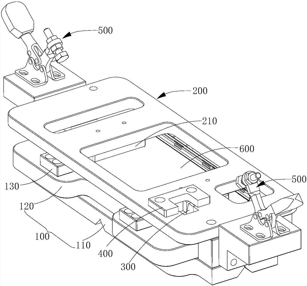
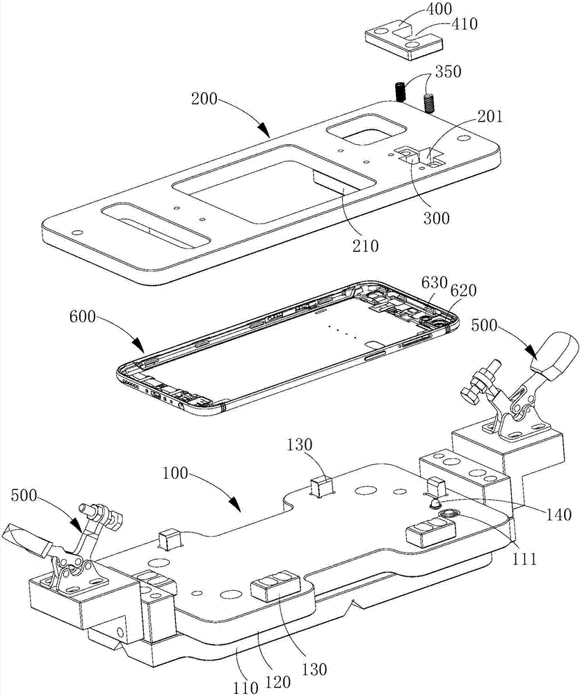
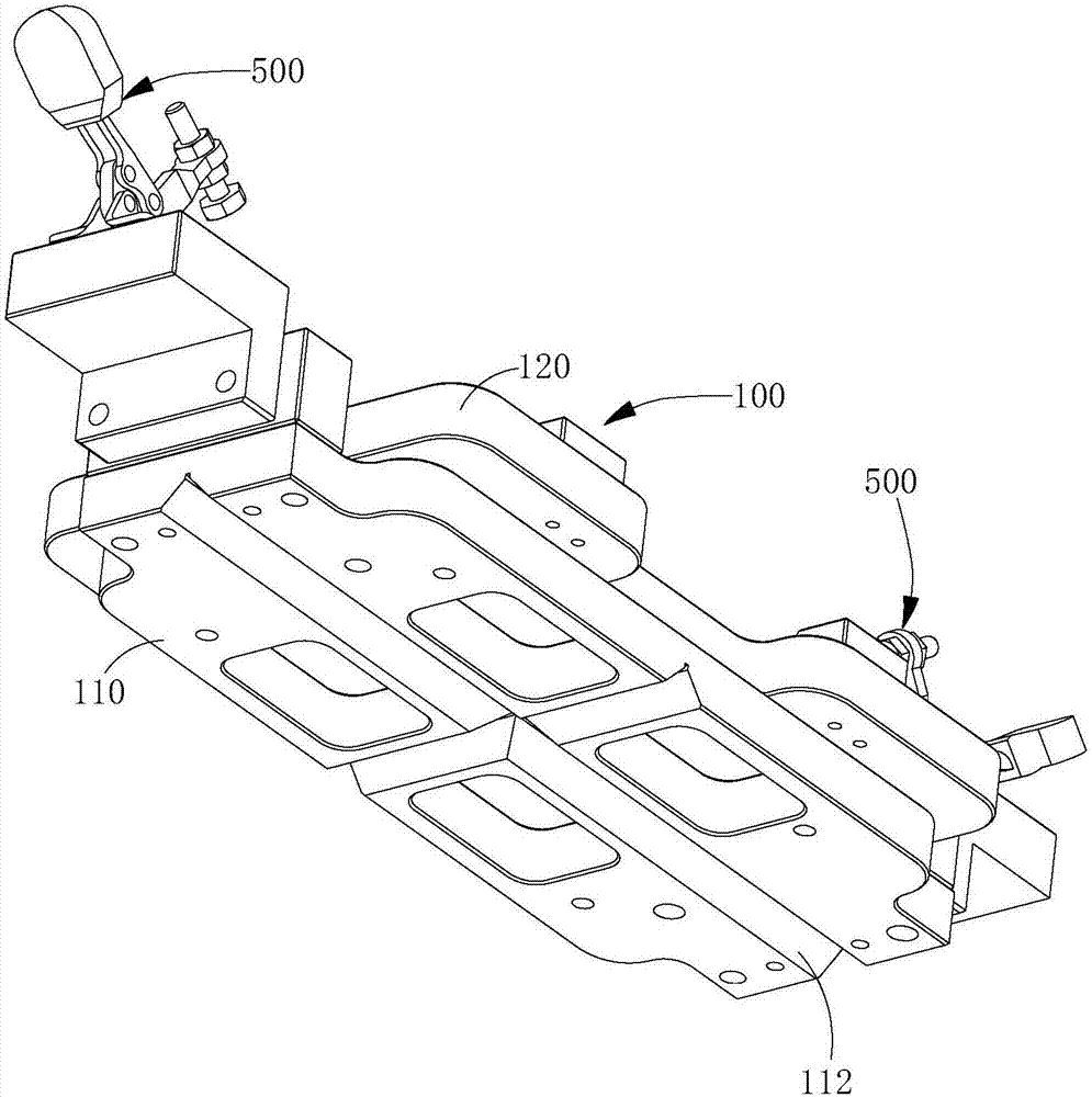
The present invention relates to a soldering jig. The soldering jig comprises a pedestal provided with a working station for positioning a workpiece; a cover plate covering a top face of the pedestal and being provided with a through hole at a position corresponding to a camera to-be-soldered part of the workpiece; a pressure head assembly arranged between the cover plate and the workpiece, the bottom part of the pressure head assembly covering a perimeter zone of a camera soldering face of the workpiece; and a clamping member arranged on the pedestal to press the cover plate and to enable the pressure head assembly to press the workpiece. According to the soldering jig provided by the invention, the pressure head assembly is arranged between the cover plate and the pedestal, and the bottom part of the pressure head assembly can cover the perimeter zone of the camera soldering face of the workpiece, so during soldering, the perimeter zone of the soldering face cannot be blackened by soldering soot, the appearance is not impacted, the soldering effect is excellent, clamping and positioning operation of the workpiece is simple, and the soldering jig is convenient to operate.

Description

technical field [0001] The invention relates to the field of welding technology, in particular to a welding jig. Background technique [0002] In the process of assembly and processing of electronic products, some components need to be welded and fixed. For example, in the process of assembly and processing of mobile phones, the camera needs to be welded to the predetermined position of the rear shell of the mobile phone. The shell is positioned and fixed, and the defect rate of products processed with existing jigs is high, and the appearance quality of the products is difficult to meet the standards. Contents of the invention [0003] Based on this, it is necessary to provide a welding jig that is easy to use and has a good welding effect. [0004] A welding fixture, comprising: [0005] a base, the base is provided with a station for fixing the workpiece; [0006] A cover plate is provided on the top surface of the base, and the cover plate is provided with a through...

Claims


Application Information

Patent Timeline
Patent Type & Authority Applications(China)
IPC IPC(8): B23K37/04
CPCB23K37/0443
Inventor 王犁冬
Owner GUANGDONG EVERWIN PRECISION TECH
Why Eureka
Try Eureka