
Truss robot guide rail assembly

A truss robot and guide rail technology, which is applied in the field of robot guide rails, can solve problems such as high installation accuracy requirements, large noise, and guide rail collisions, and achieve the requirements of reducing accuracy, reducing noise, and achieving the effect of installation

Active Publication Date: 2017-07-25
GUANGZHOU SEAHAWN IND ROBOTICS
View PDF7 Cites 7 Cited by
  • Summary
  • Abstract
  • Description
  • Claims
  • Application Information

AI Technical Summary

Problems solved by technology

At present, most domestic robots use rollers and V-shaped guide rails as moving guide rails. This guide rail requires high installation accuracy, and the robot will collide with the guide rail during operation, resulting in a lot of noise.

Method used


Image

  • Truss robot guide rail assembly
  • Truss robot guide rail assembly

Examples


Embodiment Construction

[0030] In order to make the technical problems solved by the present invention, the technical solutions adopted and the technical effects achieved clearer, the technical solutions of the embodiments of the present invention will be further described in detail below in conjunction with the accompanying drawings. Obviously, the described embodiments are only the technical solutions of the present invention. Some, but not all, embodiments. Based on the embodiments of the present invention, all other embodiments obtained by those skilled in the art without creative efforts fall within the protection scope of the present invention.

[0031] In the description of the present invention, unless otherwise clearly specified and limited, the terms "connected", "connected" and "fixed" should be understood in a broad sense, for example, it can be a fixed connection, a detachable connection, or an integrated ; It can be a mechanical connection or an electrical connection; it can be a direct...


PUM


Abstract

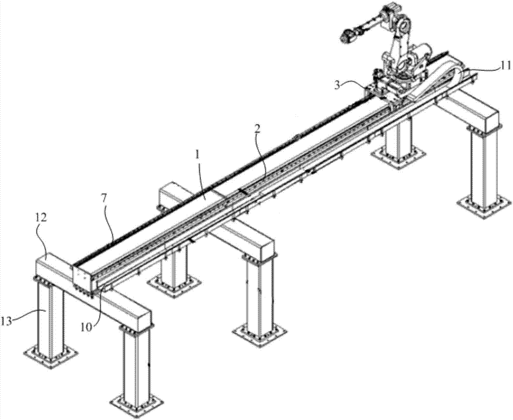
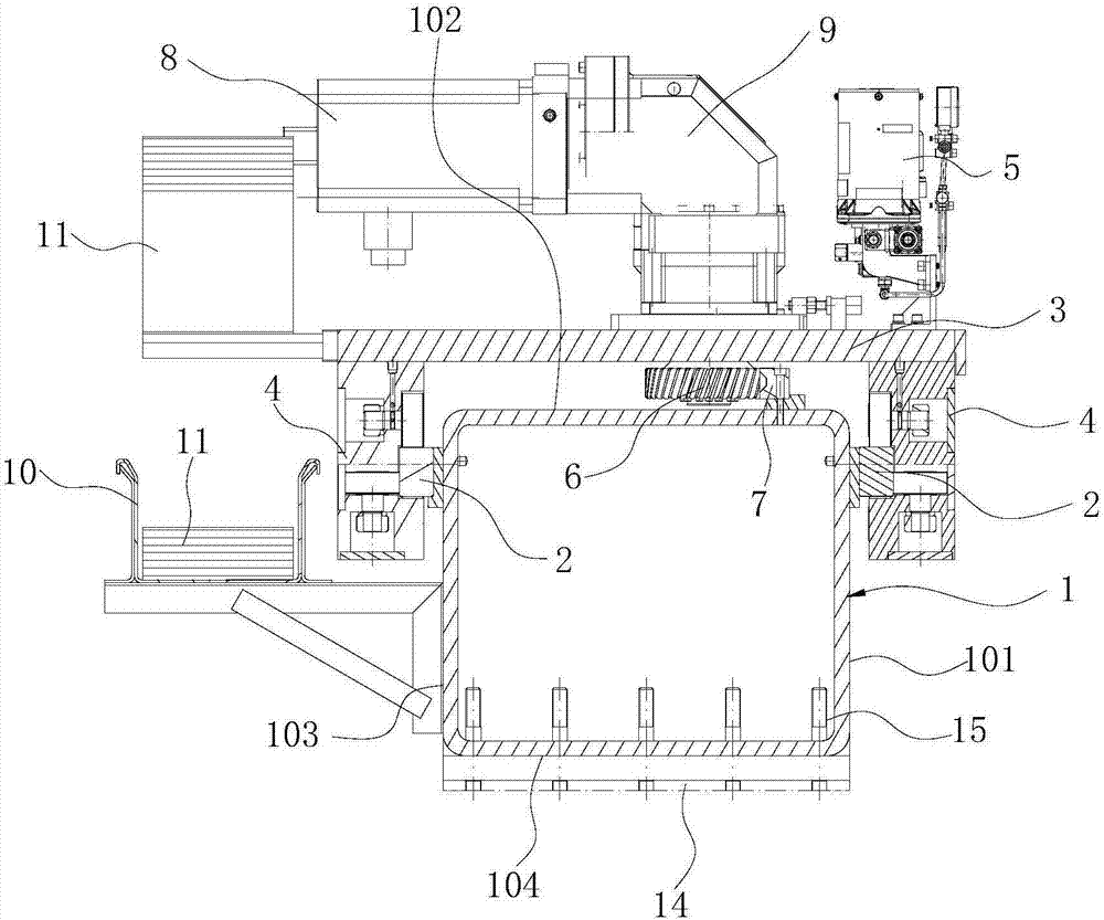
The invention discloses a truss robot guide rail assembly. The truss robot guide rail assembly comprises a truss beam, a slide platen and a driving mechanism. The opposite two sides of the truss beam are correspondingly provided with guide rails. The length of the guide rails extend along the direction of the truss beam length. The slide platen is used for mounting a robot. One side of the slide plate adjacent to the truss beam is provided with pulley blocks cooperating with guide rail gaps. The pulley blocks comprise rolling wheels located on both sides of the guide rails and conducting rolling friction to the guide rails. The distance between the two rolling wheels is adjustable. The driving mechanism is used for driving the slide platen to move on the truss beam. By setting the pulley blocks, the relationship between the slide platen and the truss beam is rolling friction so that the friction and collision between the slide platen and the guide rails during the movement of the slide platen can be reduced and the noise can be reduced, and the distance between the two rolling wheels of arranged on two sides of the guide rails is adjustable, so that the request to the accuracy during the installation of the guide rails and the pulley blocks is reduced. When the pulley blocks are mounted on the guide rails, then the distance between the two rolling wheels is adjusted to achieve the installation of the guide rails and the pulley blocks.

Description

technical field [0001] The invention relates to the technical field of robot guide rails, in particular to a truss robot guide rail assembly. Background technique [0002] At present, in domestic robot applications, when multiple processing equipments are required to work at the same time, multiple robots are generally used to complete the required work. Multiple robots work on one assembly line, requiring a lot of auxiliary equipment, which will increase the purchase cost of the equipment, and the failure rate will increase, the production efficiency cannot be guaranteed, and the floor space will be larger. [0003] Therefore, the concept of truss robot is proposed to simplify the problem of large number and high cost of robots on the assembly line. The truss robot is a fully automatic industrial equipment that can adjust the position of the workpiece or realize the trajectory movement of the workpiece. At present, most domestic robots use rollers and V-shaped guide rails...

Claims


Application Information

Patent Timeline
Patent Type & Authority Applications(China)
IPC IPC(8): B25J5/02
CPCB25J5/02
Inventor 彭勇超谢伟钢余夏洋左庆科
Owner GUANGZHOU SEAHAWN IND ROBOTICS
Learn More