
Electromagnetic insert gripper device

A gripper device and insert technology, applied in the directions of manipulators, program-controlled manipulators, chucks, etc., can solve the problems of low automation procedures and low efficiency, and achieve the effect of avoiding industrial accidents, improving efficiency and ensuring stability.

Pending Publication Date: 2017-07-25
SUZHOU SANJI FOUNDRY EQUIP
View PDF0 Cites 0 Cited by
  • Summary
  • Abstract
  • Description
  • Claims
  • Application Information

AI Technical Summary

Problems solved by technology

[0003] Inserting inserts manually will cause work-related accidents, the automation program is not high, and the efficiency is low

Method used


Image

  • Electromagnetic insert gripper device
  • Electromagnetic insert gripper device

Examples


Embodiment Construction

[0018] In order to have a clearer understanding of the technical features, purposes and effects of the present invention, specific implementations will now be described in detail with reference to the accompanying drawings.

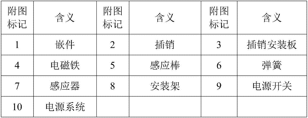
[0019] Such as figure 1 As shown, the electromagnetic insert gripper device includes a latch 2, an electromagnet 4, a latch mounting plate 3, and an induction rod 5. A plurality of latches 2 are distributed on the latch mounting plate 3, and the latch mounting plate 3 is carried on the electromagnetic through the induction rod 5. On the iron 4, the bottom end of the induction rod 5 is placed in the guide hole of the electromagnet 4 through the spring 6, the spring 6 is a cylindrical helical compression spring, the electromagnet 4 is fixed on the mounting frame 8, the electromagnet 4 is connected to the power switch 9, and the power supply The switch 9 is connected to the power system, the electromagnet 4 is a direct-acting electromagnet; the sensor 7 is i...


PUM


Abstract

The invention discloses an electromagnetic insert gripper device. A plurality of plug pins are distributed on a plug pin mounting plate. The plug pin mounting plate is carried on an electromagnet through an induction bar. The bottom end of the induction bar is arranged in a guide hole of the electromagnet through a spring. The electromagnet is fixed to a mounting frame and connected with a power switch. The mounting frame is mounted on a manipulator. The manipulator is fixed to an X-Y axis movement unit. The whole gripper device is driven through the manipulator, the plug pins are inserted into inner holes of an insert, then the electromagnet is powered on, the insert is grabbed through magnetic force of the electromagnet, the insert is attracted by the magnetic force and then transferred into a die through the manipulator, the electromagnet is powered off, the insert is separated from the plug pins and left in the die, and thus the insert is inlaid automatically; a marble base is adopted by the X-Y axis movement unit, so that stability and low oscillation in the movement process are guaranteed; and the automation degree is high.

Description

technical field [0001] The invention relates to an electromagnetic insert gripping device. Background technique [0002] At present, many products die-cast by die-casting machines need to be equipped with inserts of different materials inside. The products need to insert inserts into the mold, and then liquid aluminum is injected into the mold, so as to improve the performance of key parts and improve the product quality. longevity and cost reduction. When die-casting processes the above products, the inserts need to be pre-installed by the operator in the state of mold opening, and then the machine is turned on for die-casting. [0003] Manually inserting inserts may cause industrial accidents, and the automation program is not high and the efficiency is low. Contents of the invention [0004] The purpose of the present invention is to overcome the shortcomings of the prior art and provide an electromagnetic insert gripper device. [0005] The purpose of the present in...

Claims


Application Information

Patent Timeline
IPC IPC(8): B25J9/02B25J15/06
CPCB25J9/023B25J15/0608
Inventor 贾祥磊
Owner SUZHOU SANJI FOUNDRY EQUIP
Features
  • Generate Ideas
  • Intellectual Property
  • Life Sciences
  • Materials
  • Tech Scout
  • Unparalleled Data Quality
  • Higher Quality Content
  • 60% Fewer Hallucinations
Learn More