Hand wheel clutch for machine

A technology of clutches and handwheels, which is applied in the direction of mechanically driven clutches, clutches, and clutches that mesh with each other, and can solve problems such as difficult maintenance, difficult assembly, and increased processing costs

Inactive Publication Date: 2017-07-25
FLAIR IND ACCESSORY
View PDF6 Cites 0 Cited by
  • Summary
  • Abstract
  • Description
  • Claims
  • Application Information

AI Technical Summary

Problems solved by technology

However, the above-mentioned prior art patent application has too many parts and components in terms of structure, so in addition to causing an increase in processing costs, it will also cause problems such as difficult assembly and difficult maintenance.

Method used


Image

  • Hand wheel clutch for machine
  • Hand wheel clutch for machine
  • Hand wheel clutch for machine

Examples


Embodiment Construction

[0026] Below in conjunction with accompanying drawing, structural principle and working principle of the present invention are specifically described:

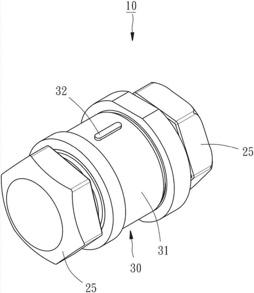
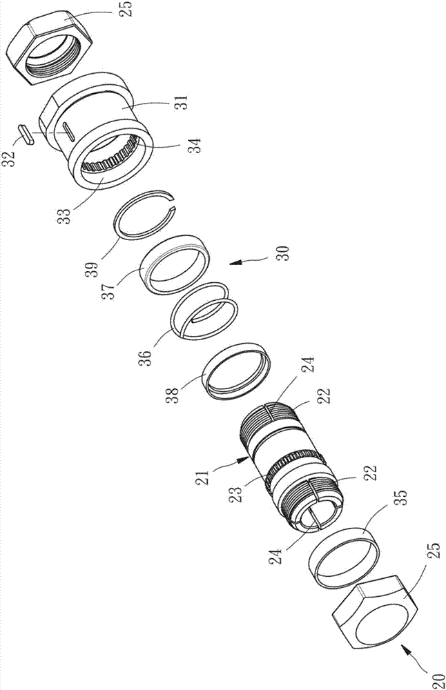
[0027] see figure 1 and 2 , the handwheel clutch 10 for machinery of the present invention includes a handwheel fixing unit 20 and a clutch unit 30 .

[0028] The handwheel fixing unit 20 has a shaft sleeve 21 and two nuts 25, wherein the shaft sleeve 21 is used to be sleeved on a handwheel shaft 12 (such as image 3 shown). Both ends of the shaft sleeve 21 have an external thread portion 22 respectively, and the outer peripheral surface of the shaft sleeve 21 has an outer ring tooth portion 23, and the outer ring tooth portion 23 is interposed between the two external thread portions 22; each nut 25 The screw is arranged on the external thread portion 22 of the shaft sleeve 21 , thereby, when the shaft sleeve 21 is sleeved on the handwheel shaft 12 and then the nut 25 is locked, the shaft sleeve 21 and the handwheel shaft ...


PUM


Abstract

A handwheel clutch for machinery, mainly including a handwheel fixing unit and a clutch unit, the handwheel fixing unit has a shaft sleeve and a nut provided on the shaft sleeve, and the shaft sleeve has an outer ring tooth , the clutch unit has a clutch part, the clutch part is movably sleeved on the shaft sleeve and has an inner ring tooth part, when the clutch part is in a first position, the inner ring gear part of the clutch part and the outer ring tooth part of the shaft sleeve The parts are separated from each other, so that the clutch part cannot drive the shaft sleeve to rotate. When the clutch part is in a second position, the inner ring gear part of the clutch part meshes with the outer ring gear part of the shaft sleeve, so that the clutch part can drive the shaft synchronously. The sleeve is rotated so as to provide a clutch effect to the handwheel.

Description

technical field [0001] The invention relates to a clutch for machinery, in particular to a handwheel clutch for machinery. Background technique [0002] General processing tools usually need to manually drive the handwheel to rotate before using the tool to process the workpiece, so that the handwheel can feed the working platform to the appropriate processing position through the handwheel shaft during the rotation process, but the handwheel and the handwheel There is no clutch design between the wheel shafts in the traditional structural configuration, so that the hand wheel is easily collided by people around, which will cause the offset of the working platform and affect the machining accuracy. [0003] In order to solve the above problems, the patent application No. M492221 of Taiwan, China is to use the control part to control the clutch effect between the operation wheel and the shaft tube. When the control part is pulled, the control part will first drive the inserti...

Claims


Application Information

Patent Timeline
IPC IPC(8): F16D11/14
CPCF16D11/14
Inventor 张胜福
Owner FLAIR IND ACCESSORY
Why Eureka
Try Eureka