Carrier synchronization method and device for parallel power generation of many inverters

A carrier synchronization and multi-inverter technology, applied in the direction of single-network parallel feeding arrangement, etc., can solve the problems that inverters cannot be used

Inactive Publication Date: 2017-07-25
EAST GRP CO LTD
View PDF6 Cites 16 Cited by
  • Summary
  • Abstract
  • Description
  • Claims
  • Application Information

AI Technical Summary

Problems solved by technology

[0005] However, because this method needs to reserve the carrier synchronization function in the early stage and needs to add complex hardware, and many old-generation inverters generally do not

Method used


Image

  • Carrier synchronization method and device for parallel power generation of many inverters
  • Carrier synchronization method and device for parallel power generation of many inverters
  • Carrier synchronization method and device for parallel power generation of many inverters

Examples


Embodiment Construction

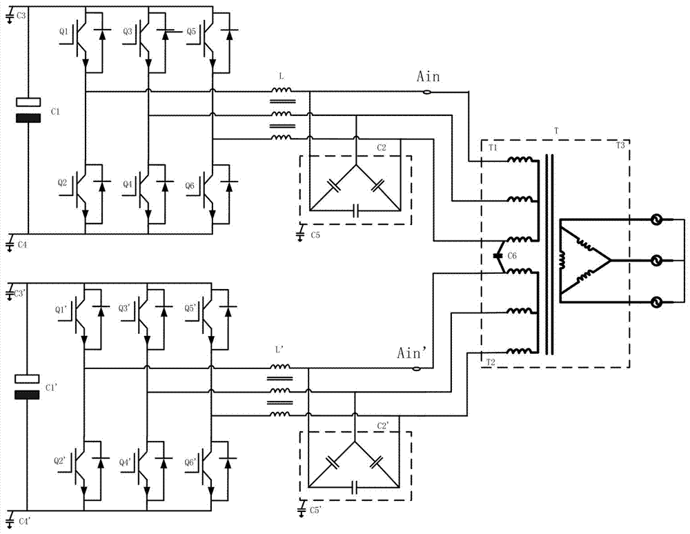
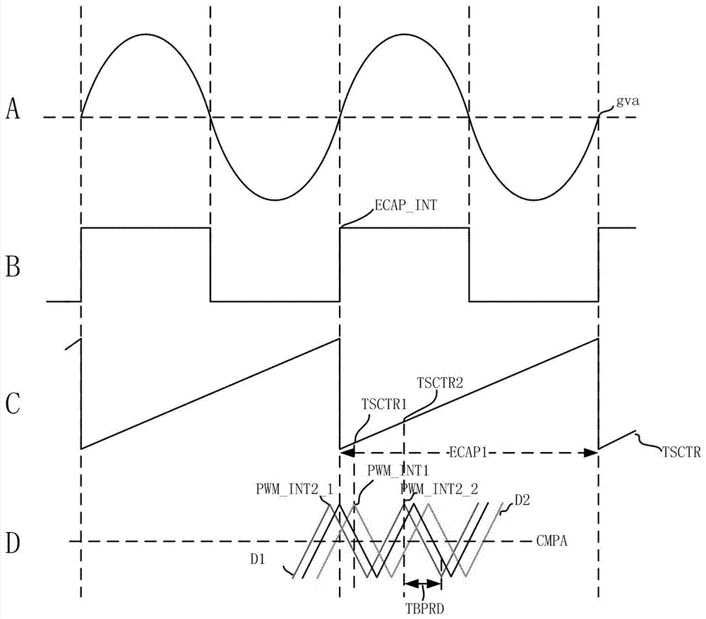
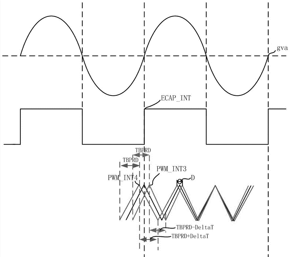
[0030] refer to figure 2 , in order to realize the carrier synchronization of the parallel power generation system, the present invention does not need to add a complex master-slave control architecture on the hardware, only figure 1 It is enough to add a comparator to the parallel power generation system shown. Specifically, one inverter is called C1, the controller of C1 is called CPU_1, the other inverter is called C2, and the controller of C2 is called CPU_2, then the capture pins of CPU_1 and CPU_2 are both connected through the same external The comparator of the transformer is electrically connected with the input terminal Ain of the A-phase wire of the transformer, and the comparator will compare the grid waveform at the input terminal Ain of the A-phase wire (ie figure 2 A waveform) into a square wave (ie figure 2 B waveform) and transmitted to each CPU, the rising edge of the square wave is the location of the zero-crossing point of the power grid.

[0031] Sin...


PUM


Abstract

The invention creates the field of new energy power generation, and particularly relates to a carrier synchronization method for parallel power generation of many inverters. A carrier frequency of an inverter C1 is same as carrier frequencies of other inverters, the carrier period is shortened, namely, the carrier frequency of the inverter C1 is increased if a carrier output from the inverter C1 lags behind a power grid waveform in a phase, and the carrier period is prolonged, namely, the carrier frequency is slowed if the carrier output from the inverter C1 is ahead of the power grid waveform in the phase. Compared with the prior art, the method has the advantage that carrier synchronization between two inverters can also be achieved without additionally arranging a traditional complicated master-slave control architecture, and circulation between two inverters is improved. The method created by the invention can be implemented by building a functional module and combining a functional module architecture and by a computer program stored in a computer readable storage medium.

Description

technical field [0001] The invention relates to the field of new energy power generation, in particular to a carrier synchronization method for multi-inverter parallel power generation. The method used in the invention can be implemented by establishing functional modules, combining them into a functional module framework, and being implemented by a computer program stored in a computer-readable storage medium. Background technique [0002] Such as figure 1 As shown, in the inverter, the CPU outputs PWM to each switch tube Q1-Q6, Q1 ' -Q6 ' The base of each switching tube is controlled by PWM to realize the inversion process of the inverter. In order to improve efficiency and save costs, at least two inverters are usually replaced by the output transformer of each inverter with the secondary winding double-split transformer T, thus forming figure 1 The parallel power generation system shown. [0003] exist figure 1 In the parallel power generation system shown, since t...

Claims


Application Information

Patent Timeline
IPC IPC(8): H02J3/38H02J3/40
CPCH02J3/38H02J3/40
Inventor 冯金生
Owner EAST GRP CO LTD
Why Eureka
Try Eureka