Spatial modulation method based on selection of receiving and transmitting antennas

A technology of spatial modulation and transmitting and receiving antennas, which is applied in space transmit diversity, diversity/multi-antenna systems, radio transmission systems, etc., and can solve problems such as low spectrum efficiency

Active Publication Date: 2017-07-25
SUN YAT SEN UNIV
View PDF5 Cites 14 Cited by
  • Summary
  • Abstract
  • Description
  • Claims
  • Application Information

AI Technical Summary

Problems solved by technology

[0003] In order to solve the above problem of low spectrum efficiency, the present invention uses the index number of the transmitting antenna and the index number of the

Method used


Image

  • Spatial modulation method based on selection of receiving and transmitting antennas
  • Spatial modulation method based on selection of receiving and transmitting antennas
  • Spatial modulation method based on selection of receiving and transmitting antennas

Examples


Embodiment 1

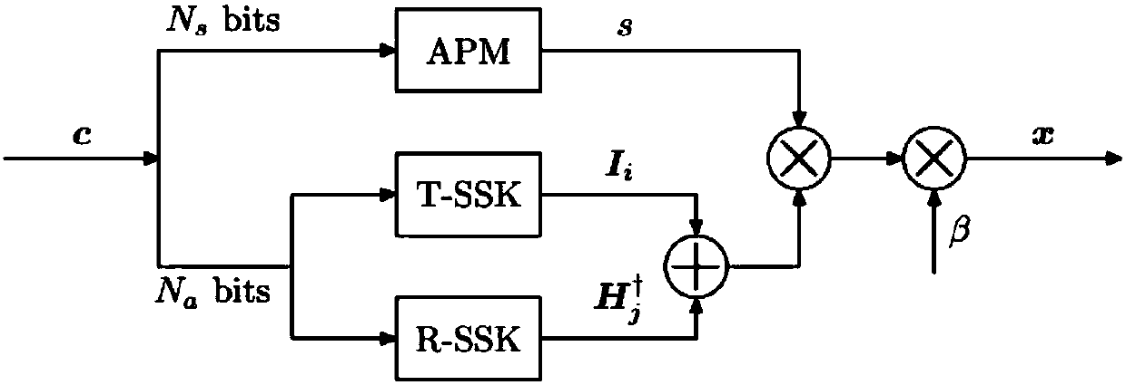
[0018] The number of transmitting antennas configured in this embodiment is M T =8, the number of receiving antennas is M R =4. i(1≤i≤M T ) root transmitting antenna transmits to the jth (1≤j≤M R ) The channel coefficient corresponding to the receiving antenna is h j,i , the wireless channel matrix for transmission Each element of is determined by the channel coefficient h j,i composed and known at both the sender and receiver. The received signal vector is That is y=Hx+z, where represents the sending vector, Is an additive Gaussian white noise vector, each element of z is independently and identically distributed, and obeys The method includes a transmitter and a receiver signal processing process, and the transmitter signal processing process includes the following steps:

[0019] (1.1) The transmitter sends a non-coded bit sequence of length N=8 each time Represents a set of N-dimensional binary finite fields; the bit stream c is divided into two parts c=...

Embodiment 2

[0028] The number of transmitting antennas configured in this embodiment is M T =8, the number of receiving antennas is M R =4. i(1≤i≤M T ) root transmitting antenna transmits to the jth (1≤j≤M R ) The channel coefficient corresponding to the receiving antenna is h j,i , the wireless channel matrix for transmission Each element of is determined by the channel coefficient h j,i composed and known at both the sender and receiver. The received signal vector is That is y=Hx+z, where represents the sending vector, Is an additive Gaussian white noise vector, each element of z is independently and identically distributed, and obeys The method includes a transmitter and a receiver signal processing process, and the transmitter signal processing process includes the following steps:

[0029] (1.1) The transmitter sends a coded bit sequence of length N=8 each time Represents a set of N-dimensional binary finite fields; the bit stream c is divided into two parts c={c ...


PUM


Abstract

The invention belongs to the field of digital wireless communication, and discloses a new spatial modulation (SM) transmission method, namely, spatial modulation (TRSM) based on selection of receiving and transmitting antennas. The method comprises the following steps: at a transmitting end, firstly dividing code word bits into two parts, mapping a part of code word bits into modulation constellation symbols through amplitude phase modulation (AMP), mapping the other part of code word bits into index numbers of the receiving and transmitting antennas through a spatial modulator, and then designing a to-be-sent spatial modulation signal vector according to the index numbers of the receiving and transmitting antennas. The spatial modulation method disclosed by the invention integrates spatial modulation (TSM) of transmitting antenna selection and the spatial modulation (RSM) of receiving antenna selection, thereby not only carrying information through the index numbers of the transmitting antenna, but also carrying information through the index number of the receiving antennas. Compared with the traditional TSM and RSM methods, the provided TRSM method has higher spectral efficiency and relatively low error beds. In addition, at a receiving end, in order to reduce the decoding complexity, the invention further provides a corresponding suboptimal soft detection algorithm.

Description

technical field [0001] The invention belongs to the field of digital wireless communication, and in particular relates to a multi-antenna transmission method, that is, spatial modulation based on the selection of transceiver antennas. Background technique [0002] Multi-antenna (MIMO) technology refers to a wireless transmission technology in which both the transmitting end and the receiving end of wireless communication use multiple antennas, which can enable the communication system to obtain higher spectral efficiency and improve transmission performance. Spatial modulation (SM) is a practical multi-antenna technology. Its basic idea is that part of the transmitted information bits can be mapped to traditional amplitude-phase modulation (APM) constellation symbols, and the other part of the information bits can be mapped to the index number of the space antenna. The antenna also has the ability to carry information bits. Currently existing spatial modulation techniques c...

Claims


Application Information

Patent Timeline
IPC IPC(8): H04B7/0413H04B7/06H04L1/06
CPCH04B7/0413H04B7/068H04L1/0612
Inventor 马啸王磊军张运鸿
Owner SUN YAT SEN UNIV
Why Eureka
Try Eureka