Liquid interface forming device

A molding device and liquid interface technology, applied in the field of 3D printing, can solve the problems of small molding format, difficult to obtain oxygen permeable film, complicated control technology, etc., and achieve the effect of fast molding speed, small force, and large printing area

Inactive Publication Date: 2017-07-28
郭东
View PDF3 Cites 8 Cited by
  • Summary
  • Abstract
  • Description
  • Claims
  • Application Information

AI Technical Summary

Problems solved by technology

It is a good technology, but the oxygen permeable membrane is not easy to obtain, the control technology is complicated, and the forming format is relatively small

Method used


Image

  • Liquid interface forming device
  • Liquid interface forming device
  • Liquid interface forming device

Examples


Embodiment 1

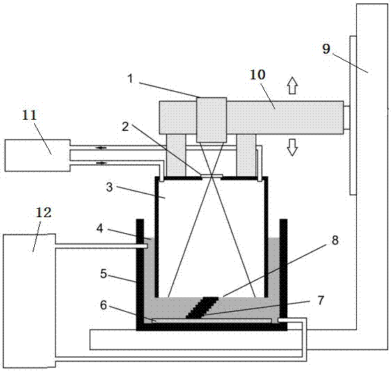
[0026] Referring to Fig. 3, on the basis of Fig. 1, the cavity 3 is connected with a first control device 11 for controlling the pressure and temperature of the gas inside, and the resin tank 5 is connected with the temperature and pressure of the liquid photosensitive resin in it. The second control device 12. The resin tank 5 is filled with liquid photosensitive resin 4, and the cavity 3 and the pattern generating device 1 stop when they move down with the first moving arm 10 and reach the molding table 6 under the control of the computer; at this time, there is only air in the sealed inflatable cavity 3 , inflate or ventilate into the sealed inflatable cavity 3 as required, when the gas-liquid interface 8 meets the requirements, the light generated by the graphic generating device 1 passes through the transparent window 2 to irradiate the gas-liquid interface 8 to cure the liquid photosensitive resin 4, and then The cavity 3 and the pattern generating device 1 move upward f...

Embodiment 2

[0028] Such as Figure 4 As shown, on the basis of Embodiment 1, a sealing ring 13 is added between the inflatable cavity 3 and the resin tank 5, so that the pressure of the gas in the sealed inflatable cavity 3 can be increased, and the pressure of the liquid photosensitive resin 4 can also be increased. pressure, so that the pressure of the gas-liquid interface 8 is greater, so that the filling speed of the liquid photosensitive resin 4 is faster. The forming speed and forming precision of the device are greatly improved.

Embodiment 3

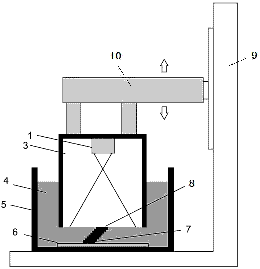
[0030] Such as Figure 5 As shown, on the basis of Embodiment 1, the inflatable cavity 3 is reduced, and the molding table 6 is made movable, and the molding table 6 is placed in the resin tank 4 through the second movable arm 14 driven by a motor and capable of moving up and down. Connect with the frame 9. When working, the forming table 6 moves downward to the set position, the cavity 3 and the pattern generating device 1 move downward to the set position, the pattern generating device 1 irradiates the gas-liquid interface 8, and the forming table 6 moves continuously with the second moving arm 14. Moving downwards for a set distance, layer by layer accumulation produces a three-dimensional shaped object 7 . The advantage of this is that the forming format can be made relatively larger.


PUM


Abstract

The invention discloses a liquid interface forming device. The liquid interface forming device comprises a frame, a resin groove, a pattern generation device and a forming table surface; an inflation cavity is provided; one end, corresponding to the forming table surface, of the cavity is opened; the cavity is sunk in the resin groove with liquid photosensitive resins; the cavity and the pattern generation device are connected with the frame through first movable arms driven by a motor and capable of moving up and down; and the forming table surface is positioned on the inner surface of the resin groove. The liquid interface forming device is fast in forming speed, low in stress of formed objects, relatively larger in printing area and high in forming precision.

Description

technical field [0001] The invention belongs to the technical field of 3D printing, in particular, it is a liquid interface forming device. Background technique [0002] Rapid prototyping is an advanced manufacturing technology developed in the 1990s. It is a technology based on digital model files to construct three-dimensional objects by printing layer by layer and accumulating layer by layer. It has a positive effect on the innovation of enterprise products, shortening the development and production cycle of products. [0003] At present, the main implementation forms of photocuring 3D printing are: laser scanning rapid prototyping, optical surface array projection photocuring, and inkjet ultraviolet photocuring. The last one is less used. The first two are mainstream technologies. SLA laser scanning rapid prototyping: This is currently the main method of industrial 3D printing. Working process: The CAD model is processed by the computer to generate the scanning path ...

Claims


Application Information

Patent Timeline
Patent Type & Authority Applications(China)
IPC IPC(8): B29C64/135B29C64/227B29C64/371B33Y30/00
CPCB33Y30/00
Inventor 郭东
Owner 郭东
Why Eureka
Try Eureka