Buffer device for pneumatic sample conveying system

A technology of pneumatic conveying and buffering device, used in conveyors, transportation and packaging, etc., can solve friction and collision force damage to pneumatic transmission pipes and samples, shorten the life of pneumatic transmission pipes and samples, change the physical properties of samples and test accuracy, etc. problems, to achieve the effect of promoting efficient operation, improving practicability and applicability, and ensuring normal development

Pending Publication Date: 2017-07-28
HUNAN SUNDY SCI & TECH DEV
View PDF6 Cites 4 Cited by
  • Summary
  • Abstract
  • Description
  • Claims
  • Application Information

AI Technical Summary

Problems solved by technology

[0004] (1) When the sample (sample bottle) is moving at high speed, the friction and collision force required to stop the sample (sample bottle) is very large, and the huge friction and collision force may damage the pneumatic transmission pipeline and the sample (sample bottle), Resulting in greatly shortened life of pneumatic transmission tubing and samples (vials)
When the pipeline breaks, it will affect the normal development of pneumatic transmission, and even paralyze the entire pneumatic transmission system in severe cases
When the sample (sample bottle) breaks, it will greatly affect the physical characteristics and accuracy of the sample
[0005] (2) The huge friction and collision force will also cause the segregation and stratification of the sample in the sample (sample bottle) or the separation or oxidation of the sample water, which may have a great impact on the subsequent sample preparation and testing, and change the quality of the sample. Physical Properties and Assay Precision
[0006] (3) A long buffer pipeline is required from high-speed motion to stop, which increases the construction cost and requires higher site requirements
[0007] (4) When the sample (sample bottle) is about to approach the destination, it will squeeze the gas in the pipeline during the impact process to form a strong pressure gas, which will cause damage to the fan at the end of the pipeline and damage the fan.

Method used


Image

  • Buffer device for pneumatic sample conveying system
  • Buffer device for pneumatic sample conveying system
  • Buffer device for pneumatic sample conveying system

Examples


Embodiment Construction

[0025] The present invention will be described in further detail below in conjunction with specific embodiments and accompanying drawings.

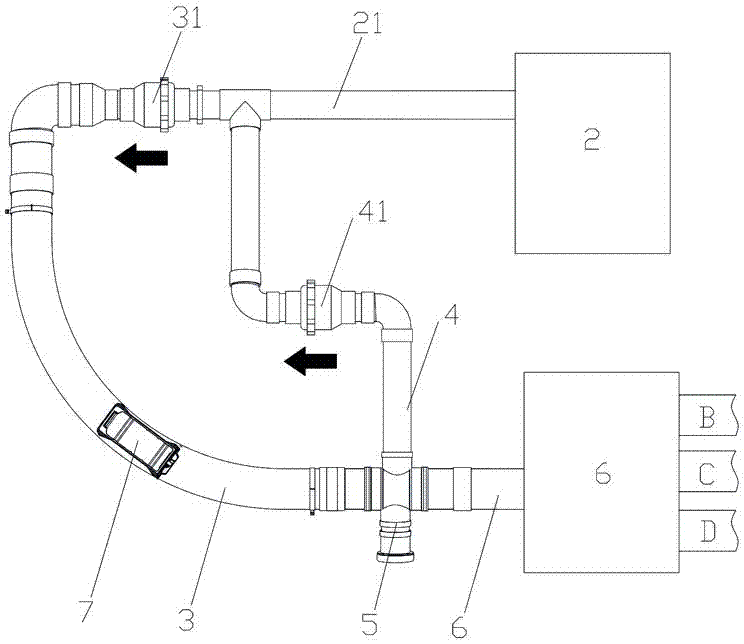
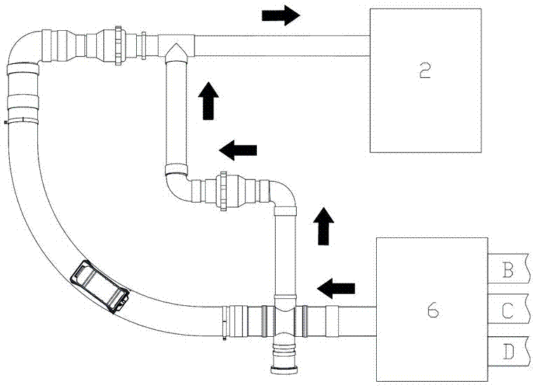
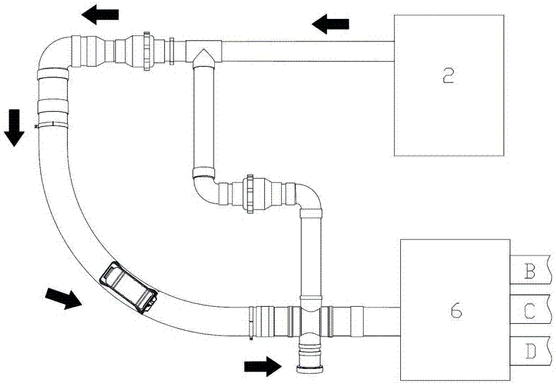
[0026] Such as Figure 1 to Figure 3 As shown, the present invention provides a buffer device for a sample pneumatic conveying system, which is arranged between the main conveying pipeline 1 and the power cabinet 2 of the pneumatic conveying system, including connecting the main conveying pipeline 1 and the power cabinet in parallel The buffer pipeline 3 and the branch pipeline 4 between the power pipeline 21 of 2. The buffer pipeline 3 is used for buffering the sample bottle 7, and the buffer pipeline 3 is provided with a forward check valve 31, so that the gas blown out by the power cabinet 2 can only flow into the buffer pipeline 3 through the forward check valve 31; The pipeline 4 is only used for adjustment, and the sample bottle 7 will not be passed into the branch pipeline 4. The branch pipeline 4 is provided with a reverse check ...


PUM


Abstract

The invention discloses a buffer device for a pneumatic sample conveying system. The buffer device is arranged between a main conveying pipeline of the pneumatic conveying system and a power cabinet, and comprises a buffer pipeline and a branch pipeline for communicating between the main conveying pipeline and a power pipe of the power cabinet in a parallel manner; a forward one-way valve is arranged on the buffer pipeline; a reverse one-way valve is arranged on the branch pipeline; when the power cabinet sucks gas, negative-pressure gas of the main conveying pipeline only can be sucked into the power cabinet by the branch pipeline to enable a sample bottle sucked from the main conveying pipeline to enter the buffer pipeline to form buffering; and when the power cabinet blows the gas, positive-pressure gas blown by the power cabinet only can be blown into the main conveying pipeline by the buffer pipeline to synchronously blow the sample bottle in the buffer pipeline into the main conveying pipeline for pneumatic conveying. The buffer device has the advantages of scientific and reasonable design, low construction cost, good buffer effect and high safety.

Description

technical field [0001] The invention mainly relates to the field of material sample collection and processing equipment, in particular to a buffer device used in a sample pneumatic conveying system. Background technique [0002] For the sampling, sample preparation, and testing of material (such as ore, coal) samples, each country has mandatory standards, and the sampling and processing of samples must be carried out in accordance with the standards. The principle of sample sampling, sample preparation, and testing work process is to gradually reduce the particle size and quality of the collected samples without destroying the representativeness of the sample, until it meets the particle size and quality of the sample in the laboratory test ( Weight) accuracy requirements, and then carry out relevant laboratory analysis on the samples that meet the requirements. For example, taking coal sampling as an example, it is actually a sampling and analysis process. The purpose of c...

Claims


Application Information

Patent Timeline
Patent Type & Authority Applications(China)
IPC IPC(8): B65G51/18B65G51/36
CPCB65G51/18B65G51/36B65G2201/0244
Inventor 肖兵球李冬军
Owner HUNAN SUNDY SCI & TECH DEV
Why Eureka
Try Eureka