Construction method and installation precision control method of steel lattice column in main engine room of ship lift

A technology of a steel lattice column and a construction method, which is applied in the vertical lifting of ship machinery, boat lifting devices, construction and other directions, can solve the problem that it is difficult to control the installation accuracy and quality of anchor bolts, displacement and deformation of embedded parts of column feet, and steel lattice columns. There are many problems such as a large number of problems, so as to achieve the effect that the production accuracy is easy to ensure, the installation height is large, and the installation accuracy requirements are high.

Inactive Publication Date: 2018-12-21
CHINA GEZHOUBA GRP MECHANICAL & ELECTRICAL CONSTR
View PDF7 Cites 0 Cited by
  • Summary
  • Abstract
  • Description
  • Claims
  • Application Information

AI Technical Summary

Problems solved by technology

The steel lattice column includes column foot embedded parts, four-tube column body and shoulder beam. The column foot embedded parts belong to the first-phase embedded parts. In the design, the column foot embedded parts of each steel lattice column are divided into four groups, with 8 pieces in each group The anchor bolts are distributed in a circle. Although the decentralized structure is simple, it is difficult to control the installation accuracy and quality between the anchor bolts and between each group.
Due to the large number of steel lattice columns, large installation height, heavy bearing capacity, and dense foundation steel mesh in the civil structure, there is a great interference to the installation and positioning between the embedded parts and the columns, and the civil pouring cannot be well avoided. Displacement and deformation of column foot embedded parts in the process

Method used


Image

  • Construction method and installation precision control method of steel lattice column in main engine room of ship lift
  • Construction method and installation precision control method of steel lattice column in main engine room of ship lift
  • Construction method and installation precision control method of steel lattice column in main engine room of ship lift

Examples


Embodiment Construction

[0038] The present invention will be further described below in conjunction with the drawings.

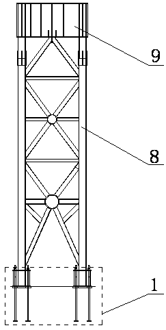
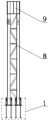
[0039] Such as figure 1 with 2 As shown, the upper structure of a group of steel lattice columns includes a four-tube column body 8 and a shoulder beam 9. The four-tube column body 8 includes four tubular columns, and the four tubular columns are welded and fixed to each other and the top ends are connected. The line forms a rectangle. The shoulder beam 9 includes an upper cover plate, a lower cover plate and a web. The shoulder beam 9 is welded to the top of the four-tube column body 8; the steel lattice column is made to be divided into column welding, shoulder beam welding and four-tube The column body and the shoulder beam are erected on multiple working surfaces, and the streamlining operation in the factory can greatly improve the production efficiency and shorten the construction period. The environment in the factory is flat and fully equipped, and the production accuracy is ea...


PUM


Abstract

The invention relates to the technical field of ship lift installation and construction, and discloses a ship lift primary machine room steel latticed column construction method and an installation precision control method. According to the steel latticed column construction method, a plurality of sets of steel latticed columns of a primary machine room can be manufactured and installed, the installation quality and the working efficiency of the steel latticed columns can be improved, and the subsequent equipment installation progress and reliability are guaranteed. Through the installation precision control method of the steel latticed columns, efficient and accurate installation and adjustment of the steel latticed columns can be achieved, construction requirements of the steel latticed columns for large installation height, large bearing capacity, high installation precision and the like are met, and the installation precision control method can be applied and popularized to construction of other steel structures.

Description

Technical field [0001] The invention relates to the technical field of installation and construction of ship lifts, and in particular to a construction method and installation accuracy control method for steel lattice columns in the main engine room of ship lifts, and is particularly suitable for the large number of steel lattice columns, large installation heights, heavy bearing capacity, The overall structure installation method and installation accuracy control method that require high installation accuracy. Background technique [0002] The Jinghong force ship lift is a new type of ship lift that uses water energy to lift the ship compartment. Its main engine room is enclosed by a steel structure. It is equipped with two spans and 36 steel lattice columns with 18 axes, and the column axis spacing is 6m. The steel lattice column is the load-bearing foundation of the main engine room bridge crane and the track beam, and its construction quality and work schedule are very import...

Claims


Application Information

Patent Timeline
Patent Type & Authority Patents(China)
IPC IPC(8): E02C5/00
CPCE02C5/00
Inventor 莫文华程建文崔慧丽徐海林吉勇
Owner CHINA GEZHOUBA GRP MECHANICAL & ELECTRICAL CONSTR
Why Eureka
Try Eureka