Variable-rail insulation door

A technology for thermal insulation doors and tracks, which is applied in windows/doors, fire doors, door/window accessories, etc. It can solve the problems of reducing the space occupied by the door storage, failing to meet the use requirements, and poor overall sealing performance, so as to achieve overall sealing performance Good, beneficial to light weight, reducing the effect of processing difficulty

Active Publication Date: 2017-07-28
SHENYANG BAOTONG DOOR
View PDF7 Cites 5 Cited by
  • Summary
  • Abstract
  • Description
  • Claims
  • Application Information

AI Technical Summary

Problems solved by technology

The track door of the first structural form adopts a single row of track, which not only saves the cost, but also has a good overall sealing performance after the door body is closed. The use requirements of the site; the track door of the second structural form reduces the occupied space of the door warehouse because the two doors are arranged side by side in the door warehouse, but because it uses double-row tracks, it has high cost and door body Disadvantages of poor overall sealing after closing
[0003] In addition, the characteristics of the sealing structure of the existing industrial special doors are: 1. It is a non-inflatable structure with a large weight (solid); the deformation range is small, so the sealing range is small; the sealing effect depends entirely on the size of the rubber strip and the rubber strip Due to the soft and hard (deformation) characteristics of the material, the relative requirements for the processing size of the rubber strip are relatively high, the cost is high, and the sealing effect is not ideal; 2. Most of them are planar open-loop or closed-loop designs, and the range of use conditions is narrow

Method used


Image

  • Variable-rail insulation door
  • Variable-rail insulation door
  • Variable-rail insulation door

Examples


Embodiment Construction

[0044] The present invention will be further described in detail below in conjunction with the accompanying drawings and specific embodiments.

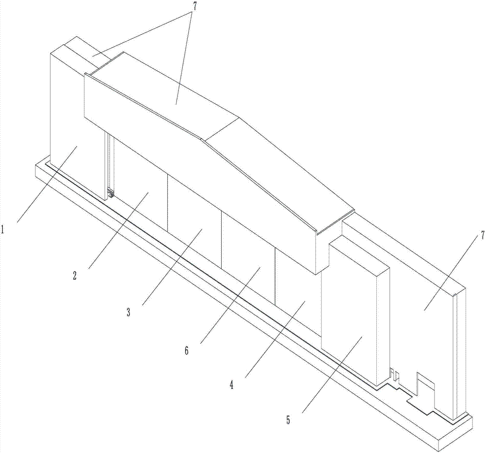
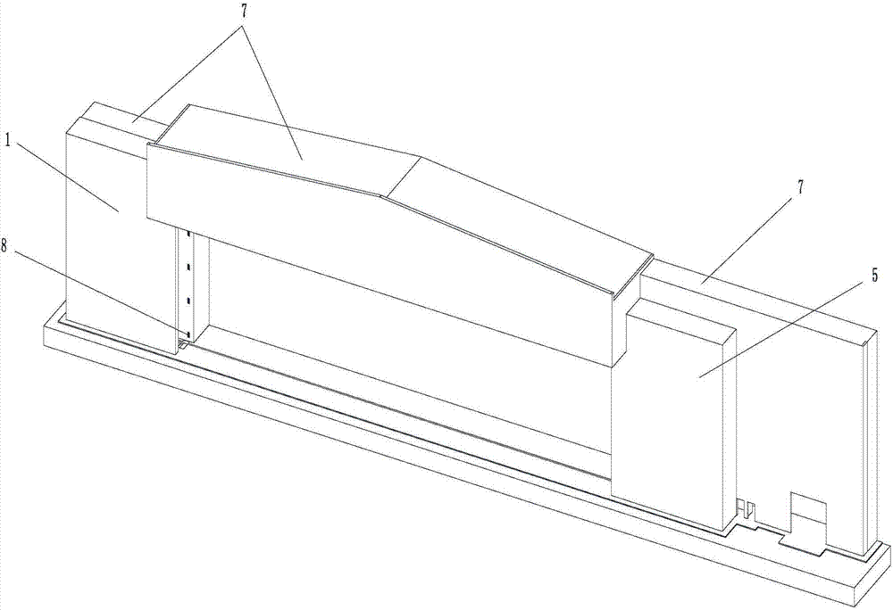
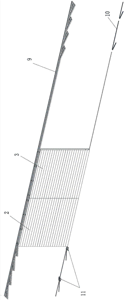
[0045] like Figure 1 to Figure 14 As shown, a track-changing heat preservation door includes an upper track 9, a lower track 10 and a door body 50; an upper guide wheel 12 is arranged on the top of the door body 50, and a running mechanism 28 is arranged at the bottom thereof, and the running mechanism 28 is made of steerable traveling wheel and the drive motor that links to each other with it; Described upper guide wheel 12 is arranged in the upper track 9, and steerable traveling wheel is arranged in the lower track 10.

[0046] Described upper track 9 comprises upper straight track 29, is respectively provided with several upper inclined tracks 30 at the two ends of upper straight track 29, and the quantity of each end upper inclined track 30 is identical with the quantity of the last guide wheel 12 of a door body; On the side of...


PUM


Abstract

The invention discloses a variable-rail insulation door and belongs to the technical field of industrial special doors. An upper guide wheel is arranged at the top of each door body, and a walking mechanism is arranged at the bottom of the upper guide wheel. The upper guide wheel is arranged in an upper track, and a turnable walking wheel is arranged in a lower track. The upper track comprises an upper straight track, and a plurality of upper oblique tracks are arranged at two ends of the upper straight track. Upper track variable-rail devices are arranged on the sides of the upper oblique tracks. The lower track comprises a lower straight track, and a plurality of lower oblique tracks are arranged at two ends of the lower straight track. Lower track variable-rail devices re arranged at the crossed positions of the lower straight track and the lower oblique tracks. A grabbing hook is arranged on the side adjacent to the door bodies, and a transverse hook connecting rod is arranged on the other side, and the grabbing hook extends out and then is matched with the transverse hook connecting rod. An adsorbing steel plate is arranged on the outer side wall of the outmost-side door body, extends out and then is matched with an electrical control permanent magnetic chuck built on a wall. Upper, left, right and lower inflating rubber tubes of the door bodies are communicated to form an integrated inflating rubber tube communicated with an air supply system.

Description

technical field [0001] The invention belongs to the technical field of industrial special doors, and in particular relates to a track-changing thermal insulation door. Background technique [0002] At present, there are two types of structure forms of the existing track doors, and the track doors with four door bodies are taken as an example for description below. One type of structure is to use a single row of tracks. When entering the warehouse, the four doors are separated from the middle. The two doors on the left enter the left door storage, and the two right doors enter the right door storage. Among them, two doors are arranged side by side; another structure is to use double-row tracks, and two doors are set in each row of tracks. When entering the warehouse, the two doors in one track are separated from the middle, and one enters the left door. The other enters the door library on the right, and in the door library, two door bodies are set side by side. The track d...

Claims


Application Information

Patent Timeline
Patent Type & Authority Applications(China)
IPC IPC(8): E06B3/46E06B5/16E06B7/23E05D13/00E05D15/06E05F15/632
CPCE05D13/00E05D15/0621E05F15/632E06B3/4636E06B5/16E06B5/164
Inventor 王兴徐忠
Owner SHENYANG BAOTONG DOOR
Why Eureka
Try Eureka