Supercharge Your Innovation With Domain-Expert AI Agents!

Well depth detecting device for ground-source heat pump

A technology of ground source heat pump and detection device, which is applied in the directions of measurement, wellbore/well components, earth-moving drilling, etc., can solve the problems such as the influence of heat exchange surface, the difficulty of detection of hidden engineering such as the depth of drilling and the amount of down pipe, etc. Easy to make, short detection time, easy to implement

Pending Publication Date: 2017-07-28
ANHUI KEEN NEW ENERGY
View PDF8 Cites 0 Cited by
  • Summary
  • Abstract
  • Description
  • Claims
  • Application Information

AI Technical Summary

Problems solved by technology

[0003] However, in the construction process of ground-source heat pump drilling and running pipes, it is difficult to detect hidden works such as well drilling depth and pipe running volume, so the actual pipe running volume has a direct impact on the heat exchange surface required by the design.

Method used


Image

  • Well depth detecting device for ground-source heat pump

Examples


Embodiment

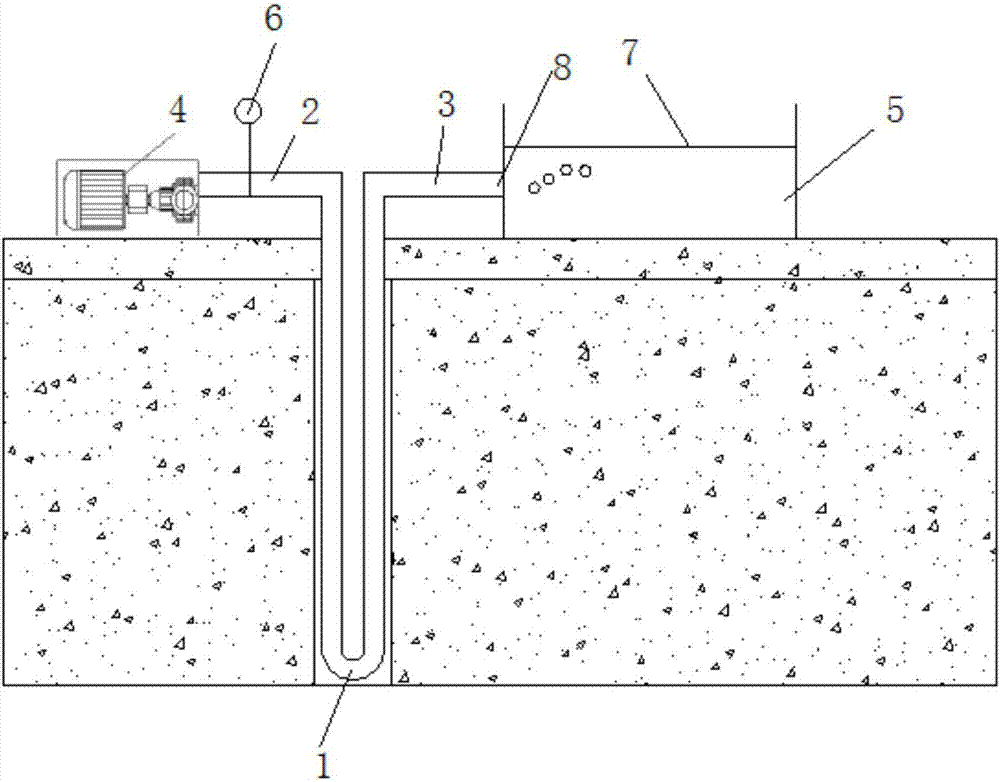
[0015] Take the measurement of the ground source heat pump well depth of 100 meters as an example:

[0016] 1. Calculate the pressure on one end of the DN32 PE-U buried pipe full of water for 100 meters until there is no water overflow at the other end of the PE-U buried pipe; use the formula: F=PS=ρgh.πr²=1.134 MPa; therefore, it is known that when the U-shaped PE pipe with a DN32 caliber is subjected to a pressure of 1.1MPa, water will no longer overflow.

[0017] 2. Connect one end of the DN32 PE buried pipe filled with water to the air compressor through the connecting pipe, and install a pressure gauge on the connecting pipe; the other end of the PE buried pipe is connected to the water tank through the connecting pipe ;Use the air compressor to pressurize the U-shaped pipe. At this time, water will flow into the tank at the other end of the U-shaped buried pipe, and continue to pressurize until the water surface line in the tank is observed to have bubbles constantly pop...


PUM


Abstract

The invention discloses a well depth detecting device for a ground-source heat pump. The well depth detecting device comprises a U-shaped buried pipe, the two ends of the U-shaped buried pipe extend out of the ground and are each horizontally connected with a connecting pipe, one end of the U-shaped buried pipe is connected with an air compressor through the corresponding connecting pipe, the other end of the U-shaped buried pipe is connected with a water filling nozzle of a transparent water tank through the corresponding connecting pipe, and the connecting pipe between the air compressor and the U-shaped buried pipe is further provided with a pressure meter; and the U-shaped buried pipe is full of water in advance. The well depth detecting device for the ground-source heat pump is simple, practical, easy to manufacture and implement and short in detecting time.

Description

technical field [0001] The invention relates to the field of ground source heat pump drilling detection, and mainly relates to a ground source heat pump well depth detection device. Background technique [0002] The ground source heat pump system uses water and ground energy (ground water, soil, surface water) to exchange cold and heat through buried pipes, thereby exchanging cold and heat. In the early stage of construction, it is necessary to conduct soil thermal response experiments on the well-drilled land to measure the heat transfer per linear meter of the buried pipe in the well-drilled land in summer and winter, and determine the number of wells to be drilled according to the design load of the above-ground buildings and depth. Therefore, in actual construction, it is necessary to ensure that the depth of drilling and the amount of pipe running meet the design requirements, so as to ensure the heat exchange effect of the ground source heat pump system used by users....

Claims


Application Information

Patent Timeline
IPC IPC(8): E21B47/04
CPCE21B47/04
Inventor 梅俊吴炎冰胡静静许龙常安凯
Owner ANHUI KEEN NEW ENERGY
Features
  • R&D
  • Intellectual Property
  • Life Sciences
  • Materials
  • Tech Scout
  • Unparalleled Data Quality
  • Higher Quality Content
  • 60% Fewer Hallucinations
Learn More