High-precision rope driving device

A rope-driven, high-precision technology, applied in transmission devices, friction transmission devices, manufacturing tools, etc., can solve the problems of low control precision, affecting circuit layout, and high cost, so as to improve the accuracy of rope output and improve reconfigurability performance and improve control accuracy

Active Publication Date: 2017-07-28
UNIV OF SCI & TECH OF CHINA
View PDF8 Cites 18 Cited by
  • Summary
  • Abstract
  • Description
  • Claims
  • Application Information

AI Technical Summary

Problems solved by technology

Cable-driven parallel robots are being widely used in various operating mechanisms. The position and posture of the braking platform in the work space are controlled by controlling the output length of the rope; The tension on the rope; most of the existing rope-driven parallel mechanism driving devices cannot integrate measuring devices. The traditional measurement method is to measure by connecting the rope and the tension sensor in series
However, the application range is narrow, the measurement effect is poor, and the circuit layout is affected
[0003] The domestic patent application No. 201410146203.1 discloses a cable winding device with the function of measuring the tension force. The device is composed of a driving device installed on the slide table and a measuring device fixed on the platform. The measuring device has a complicated structure. And it needs another motor to control the moving reel, which is more costly; it does not have the function of rope guidance, and needs to rely on other guide devices to guide the direction of rope pulling;
[0004] The domestic patent application No. 201110026500.9 discloses a rope-driven parallel robot that can realize rapid reconfiguration. The device is composed of multiple sets of drive modules, reversing devices and output devices. However, since there is no real-time measurement of tension, the control accuracy is relatively low. Low cost, complex structure, difficult installation and maintenance, and higher cost

Method used


Image

  • High-precision rope driving device
  • High-precision rope driving device

Examples


Embodiment Construction

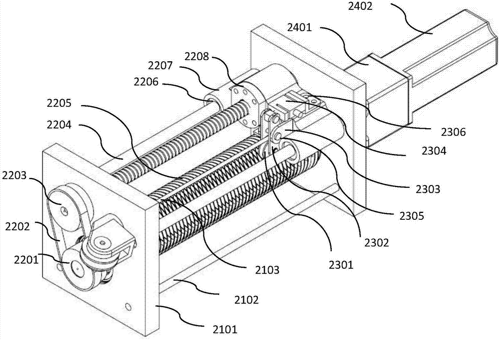
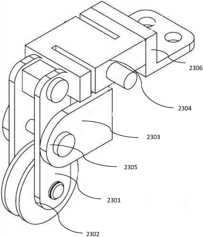
[0027] In this example, if figure 1 As shown, a rope drive device for a multi-configuration rope-driven parallel robot includes: a pair of main body brackets 2101, a pair of support rods 2102, ropes 2103, a rope guiding mechanism 2200, a universal export mechanism 2500, and a real-time tension measuring mechanism 2300 and a servo drive 2400;

[0028] The rope guiding mechanism 2200 includes: a pair of supporting optical shafts 2204, a grooved reel 2205, a driving screw 2208, a moving slide 2207, a linear bearing 2206, a timing belt 2202, a timing belt driven wheel 2203 and a timing belt driving wheel 2201; The supporting optical shaft 2204 and the driving screw 2208 have the function of load support, and can pull the moving slide 2207 to move in the horizontal direction; the number of supporting optical shaft 2204 and driving screw 2208 can be adjusted according to the actual task load requirements, or can Using a linear guide rail to replace the supporting optical axis 2204 ...


PUM


Abstract

The invention discloses a high-precision rope driving device. The high-precision rope driving device is characterized by comprising a pair of main body brackets, a pair of support rods, a rope, a rope traction mechanism, an universal derivation mechanism, a real-time tension measuring mechanism and a servo driving device; in the driving process, the rope traction mechanism guarantees sequential winding or releasing of the rope on a groove carving drum; at the same time, the upper tension of the rope is detected; the tension of the rope is precisely controlled and output; and the rope is leaded to a target working position through the universal derivation mechanism. The high-precision rope driving device can improve the position control precision and the tension control precision of the driving rope, and improves the applicability and the economic benefit through the universal derivation mechanism by reducing other auxiliary guide equipment.

Description

technical field [0001] The present invention relates to a rope driving device, in particular to a high-precision rope driving device, and in particular to the field of rope-driven parallel robots; Background technique [0002] The rope-driven parallel robot mainly includes three parts: a rope-driven device, a flexible rope, and a moving platform; the rope-driven parallel robot has the advantages of large working space, strong load capacity, fast reconfigurability, and modular design. The advantages of the rope drive make the target The working range of the working platform is larger and the movement speed is faster. Cable-driven parallel robots are being widely used in various operating mechanisms. The position and posture of the braking platform in the work space are controlled by controlling the output length of the rope; Pulling force on the rope; most of the driving devices of the existing rope-driven parallel mechanism cannot integrate a measuring device. The tradition...

Claims


Application Information

Patent Timeline
Patent Type & Authority Applications(China)
IPC IPC(8): F16H37/12F16H19/02B25J9/08B25J9/10
CPCB25J9/08B25J9/104F16H19/0618F16H37/12
Inventor 尚伟伟张飞丛爽张彬
Owner UNIV OF SCI & TECH OF CHINA
Why Eureka
Try Eureka