Primary air system

A fresh air system, fresh air technology, applied in ventilation systems, air conditioning systems, ventilation and heating energy recovery systems, etc., can solve problems such as high cost, complex structure and control, and complex structure

Active Publication Date: 2017-07-28
GREE ELECTRIC APPLIANCES INC
View PDF11 Cites 13 Cited by
  • Summary
  • Abstract
  • Description
  • Claims
  • Application Information

AI Technical Summary

Problems solved by technology

[0005] The existing solid dehumidification technology is mainly used in the dehumidification of the rotor, the air duct is fixed, and the moisture absorption and regeneration are realized through the rotation of the rotor, the structure is complex and the cost is high
In the few systems that use sprayed adsorption layer heat exchangers for dehumidification, the air ducts are also fixed. Multiple air valves are set on the air intake and return air ducts to control the flow direction of the new return air. The structure and control are relatively complicated.

Method used


Image

  • Primary air system
  • Primary air system
  • Primary air system

Examples


no. 1 example

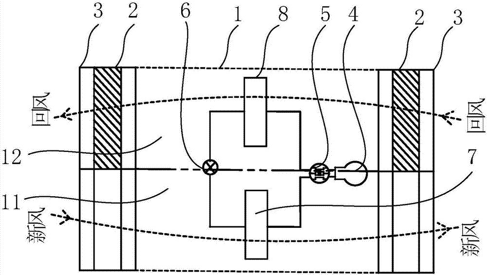
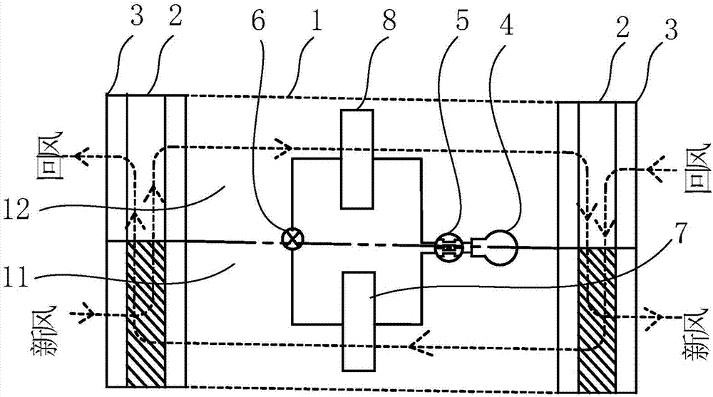
[0063] Such as figure 1 , figure 2 and 4 As shown, the rotating component may include a reversing air duct main body 23 and a rotating shaft, and the reversing air duct main body 23 may be driven to rotate relative to the main air duct 1 by the rotating shaft. The reversing air channel main body 23 may include a first air channel and a second air channel. The reversing air channel main body 23 is in the first working mode when it rotates relative to the main air channel 1, and fresh air enters the first cavity 11 through the first air channel. The return air of the second cavity 12 is discharged through the second air channel, and the reversing air channel 2 is in the second working mode relative to the main air channel 1, and the fresh air enters the second cavity 12 through the first air channel, and the first cavity The return air of 11 is discharged through the second air duct.

[0064] Such as Figure 4 , Figure 5 , Figure 6 As shown, the first air channel may in...

no. 2 example

[0107] Such as Figure 11 , Figure 12 As shown, in the second embodiment, the rotating part may include a windshield structure, the windshield structure may be arranged in the reversing air duct 2, and the windshield structure can rotate relative to the main air duct 1 to allow fresh air to enter the first cavity 11 or the second cavity 12, the return air is discharged through the second cavity 12 or the first cavity 11.

[0108] Such as Figure 13 As shown, the reversing air passage 2 may include a first air chamber 26 and a second air chamber 27, the first air chamber 26 may be provided with a fifth air passage and a sixth air passage, and the second air chamber 27 may be provided with a The seventh and eighth air passages. The windshielding structure may include a first windshielding structure 24 and a second windshielding structure 25 .

[0109] Such as Figure 11 , Figure 12 As shown, the first windshield structure 24 can rotate relative to the main air duct 1 to ...


PUM


Abstract

The invention relates to a primary air system. The primary air system comprises a main body air duct and reversing air ducts; the main body air duct comprises a first cavity and a second cavity; moisture absorbing materials capable of absorbing moisture for air flows are arranged in both the first cavity and the second cavity; each reversing air duct comprises a movable part, and the movable part can move relative to the main body air duct to enable the reversing air duct has at least two working modes; when the reversing air ducts are in the first working mode, primary air is sent into a room via the first cavity, the moisture absorbing material in the first cavity can absorb the moisture, and return air is exhausted out of the room via the second cavity; when the reversing air ducts are in the second working mode, the primary air is sent into the room via the second cavity, and the return air is exhausted out of the room via the first cavity; the moisture absorbing material in the second cavity can absorb the moisture; and the moisture absorbing material in the first cavity can be regenerated. Switching of moisture absorption and regeneration of the moisture absorbing materials is realized through switching of the reversing air ducts between the first working mode and the second working mode, and dehumidified primary air can be continuously supplied into the room.

Description

technical field [0001] The invention relates to the field of air conditioning, in particular to a fresh air system. Background technique [0002] With the increasing popularity of air-conditioning, in addition to basic cooling and heating functions, people's requirements for improving the quality of the indoor environment and the comfort of the air-conditioning system are also getting higher and higher. The radiant air-conditioning system is used in conjunction with the fresh air dehumidification system, which can just meet people's requirements for comfort and air quality. [0003] However, traditional fresh air dehumidifiers use vapor compression cooling and dehumidification technology to focus on the sensible heat and latent heat load of fresh air, resulting in high energy consumption of the unit, which deviates from the national energy-saving and emission-reduction policy. Solid dehumidification fresh air air conditioner, spray an adsorption layer on the surface of the ...

Claims


Application Information

Patent Timeline
Patent Type & Authority Applications(China)
IPC IPC(8): F24F7/08F24F3/14F24F13/30F24F12/00
CPCF24F3/1423F24F7/08F24F12/006F24F13/30F24F2003/144
Inventor 邓李娇李欣叶强蔚
Owner GREE ELECTRIC APPLIANCES INC
Why Eureka
Try Eureka