Test tube dryer

A dryer and test tube technology, which is applied in the directions of drying, dryer, drying gas arrangement, etc., can solve the problems of energy waste, difficult access, and long time required for the dryer, and achieve good drying effect and convenience. The effect of recycling and reducing energy waste

Inactive Publication Date: 2017-07-28
卢晓鹏
View PDF0 Cites 3 Cited by
  • Summary
  • Abstract
  • Description
  • Claims
  • Application Information

AI Technical Summary

Problems solved by technology

In order to avoid the influence of water on the experimental data, the water in the test tube must be removed before use, and the speed of natural evaporation is relatively slow, and water stains will be left. For some experiments that require high precision, the remaining water on the test tube Water stains will affect the results of the analysis, and in the process of natural air drying, the dust in the air will adhere to the test tube due to the long-term wetting of the inner wall of the test tube, causing re-contamination of the test tube. In order to ensure the accuracy of the experimental data, no Do not clean again, time-consuming and labor-intensive
[0003] The commonly used method of drying the water on the inner wall of the test tube is to dry the test tube at a high temperature in a constant temperature drying box, but it takes a long time, and there is no special test tube rack in the drying box, and there will still be water stains in the flat test tube, while The temperature of the test tube after drying is high, it is difficult to handle, and it is easy to break the test tube. In order to quickly dry the test tube, a hair dryer is often used to blow hot air directly at the test tube mouth, but the test tube mouth is small, and the hot air blown by the hair dryer is not easy to blow in. In the test tube, sometimes it may even cause burns to the hands. During the drying process of the tubular dryer, the water droplets on the glass instrument cannot be discharged in time, which will cause energy waste for the dryer, and some of them are drying There is a water receiving plate under the water receiving plate, and a water diversion pipe is set at the bottom of the water receiving plate, and the water diversion pipe flows to the drain outlet, but it is provided with a drain outlet, which must be close to the water tank, and the position of the dryer is limited

Method used


Image

  • Test tube dryer
  • Test tube dryer
  • Test tube dryer

Examples


Embodiment

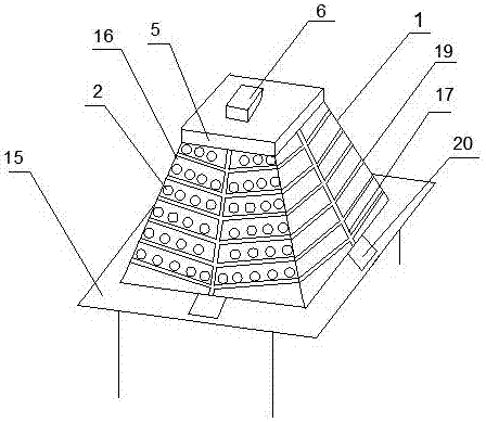
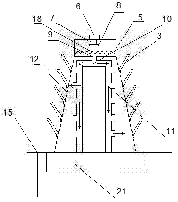
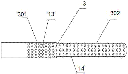
[0025] A test tube dryer, the dryer 1 is a hollow square prism structure, each wall plate 16 of the dryer 1 is provided with a drainage channel, and the drainage channel includes The vertical drainage groove 17 and several branch drainage grooves 19 that are upwardly radiating to both sides of the wall plate 16, the branch drainage groove 19 is connected with the vertical drainage groove 17, and a through hole is provided above each branch drainage groove 19 2. A flanging hole plug 4 is embedded in the through hole 2. The flanging hole plug 4 is a hollow structure with a small diameter at one end and a large diameter at the other end. The end with a small diameter is connected to the drying pipe 3 through threads;

[0026] The top of the dryer 1 is a heating and blowing mechanism, including a housing 5, a motor 6 arranged on the housing, a fan 8 connected to the motor 6 through a rotating shaft 7, and a fan 8 connected to the housing 5 is arranged below the fan 8. The heating ...


PUM


Abstract

The invention discloses a test tube dryer. The dryer is a hollow rectangular platform structure. Each wall plate of the dryer is provided with a drainage channel. The drainage channel includes a vertical drainage groove arranged on the wall plate and There are several branch drainage grooves that radiate upward to both sides of the wall plate. The branch drainage grooves are connected with the vertical drainage grooves. There is a through hole above each branch drainage groove, and a flanging hole plug is embedded in the through hole. The side hole plug is hollow in the middle, one end has a small diameter and the other end has a large diameter, and the end with a small diameter is connected to the drying pipe through threads; The motor and the fan connected to the motor through the rotating shaft are provided with a heating wire connected to the inner wall of the housing under the fan, and an air outlet connected to the inside of the dryer cavity is provided under the housing, and the air outlet is connected to the air supply through the manifold. The air supply channel corresponds to the inner surface of the wall through the branch pipe. The dryer can quickly evaporate the residual moisture in the test tube, and the water in the test tube can flow down through the drainage channel and be recovered.

Description

technical field [0001] The invention belongs to the field of chemical utensils and equipment, in particular to a test tube dryer. Background technique [0002] In various experiments, the test tube is a basic experimental equipment commonly used to assemble various solutions. It is generally reused many times after cleaning, and the presence of water in the cleaned test tube affects the accuracy of the experimental data. In order to avoid the influence of water on the experimental data, the water in the test tube must be removed before use, and the speed of natural evaporation is relatively slow, and water stains will be left. For some experiments that require high precision, the remaining water on the test tube Water stains will affect the results of the analysis, and in the process of natural air drying, the dust in the air will adhere to the test tube due to the long-term wetting of the inner wall of the test tube, causing re-contamination of the test tube. In order to en...

Claims


Application Information

Patent Timeline
Patent Type & Authority Applications(China)
IPC IPC(8): F26B9/10F26B21/00
CPCF26B9/10F26B21/004F26B21/007
Inventor 卢晓鹏
Owner 卢晓鹏
Why Eureka
Try Eureka