
High tension electroscope

An electroscope, high-voltage technology, applied in the direction of instruments, measuring electrical variables, measuring current/voltage, etc., can solve the problems of increasing malignant misoperations and personal electric shock casualties, unable to guarantee lines, personal electric shock casualties, etc., to reduce personal electric shock casualties. The effect of reducing the risk of falling objects hurting people and avoiding malignant misuse

Pending Publication Date: 2017-07-28
QINGYUAN POWER SUPPLY BUREAU OF GUANGDONG POWER GRID CO LTD
View PDF6 Cites 0 Cited by
  • Summary
  • Abstract
  • Description
  • Claims
  • Application Information

AI Technical Summary

Problems solved by technology

During the period from when the contact electrode is detached from the tested conductor to when the grounding wire is installed, there is no guarantee that the line will not become charged due to power transmission, and there is a certain risk of vicious misoperation of the "charged grounding wire" and the risk of personal electric shock and injury
[0003] An insulating rod more than one meter long is connected to the back of the high-voltage electroscope. After the electric test is completed, whether it is passed back to the ground with a sling or disassembled and put into a tool bag, it takes a relatively long time, and it is difficult to meet the "Safety Regulations" The requirement that "the grounding wire should be installed immediately after the line experience proves that there is no voltage" has increased the risk of vicious misoperation and personal electric shock to a certain extent.

Method used


Image

  • High tension electroscope

Examples


Embodiment 1

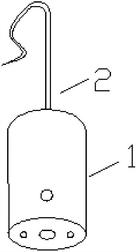
[0022] Such as figure 1 As shown, a high-voltage electroscope includes an electroscope 1 and a contact electrode 2. One end of the contact electrode 2 is fixed on the electroscope 1, and the other end of the contact electrode 2 is provided with a lifting mechanism. The high-voltage electroscope passes through The detachment mechanism is hung on the conductor under test to realize the passage from the conductor under test to the electroscope 1 .

[0023] The detachment mechanism is a hook structure, preferably, the detachment mechanism is an S-shaped hook structure; the detachment mechanism and the contact electrode 2 are integrally formed, and both are elastic metal structures that are not easily deformed plastically.

[0024] Wire grooves are arranged in the lifting mechanism, and the layout of the wire grooves on the lifting mechanism is narrow near the two ends of the lifting mechanism and wide at the middle part of the lifting mechanism.

[0025] When the high-voltage ele...


PUM


Abstract

The invention provides a high tension electroscope. According to the invention, a contact electrode is changed into a hook type structure, so after it is verified that a wire does not has voltage, the electroscope can be directly hung to the to-be-verified wire, and after a grounding wire is installed, the electroscope is taken off, so the interval time from the completion of electricity verification to installation of the grounding wire is shortened and operation efficiency is improved. If electricity is delivered suddenly before the installation of the grounding wire, the electroscope hung on the wire will give out a sound-light alarm to inform a worker that the circuit is electrified, so the worker is prevented from carrying out misoperation of installing the electrified grounding wire, and the risk of an injury or death of the worker caused by an electric shock is reduced. The wire can be buckled in a wire groove through an S-type structure in a hook position of the contact electrode, so the wire is prevented from been swung to cause falling off of the electroscope during installation of the grounding wire, and risks of people hurts caused by falling objects and damage of the electroscope are reduced. Through an anti-skid flat type structure on the inner surface in the hook place, the frictional force between the hook and the wire is increased and the electroscope is prevented from sliding along the wire to a place where the worker fails to touch.

Description

technical field [0001] The invention relates to the field of high-voltage electroscope equipment, and more specifically, to a high-voltage electroscope. Background technique [0002] The contact electrodes of common high-voltage electroscopes are needle-type structures. When testing electricity on a tower, it is necessary to artificially apply external force to make it contact with the wire for a short time. After checking that there is no voltage, it is necessary to put away the electroscope before installing the grounding wire. During the period from when the contact electrode is detached from the tested conductor to when the grounding wire is installed, there is no guarantee that the line will not become charged due to power transmission, and there is a certain risk of vicious misoperation of the "charged grounding wire" and the risk of personal electric shock and injury. [0003] An insulating rod more than one meter long is connected to the back of the high-voltage elec...

Claims


Application Information

Patent Timeline
IPC IPC(8): G01R19/155
CPCG01R19/155
Inventor 俞发强
Owner QINGYUAN POWER SUPPLY BUREAU OF GUANGDONG POWER GRID CO LTD
Features
  • Generate Ideas
  • Intellectual Property
  • Life Sciences
  • Materials
  • Tech Scout
  • Unparalleled Data Quality
  • Higher Quality Content
  • 60% Fewer Hallucinations
Learn More