Infrared projection system

A technology of infrared projection and infrared light, which is applied in the field of projection display technology and human-computer interaction, can solve the problems that the brightness of incandescent light sources cannot meet the requirements, and the system is complicated, so as to avoid the need to repeatedly correct the operation of infrared light and simplify the system , Realize the effect of human-computer interaction operation

Inactive Publication Date: 2017-07-28
IVIEW DISPLAY SHENZHEN CO LTD
View PDF5 Cites 9 Cited by
  • Summary
  • Abstract
  • Description
  • Claims
  • Application Information

AI Technical Summary

Problems solved by technology

However, the entire system in this way is too complicated, and the infrared light source needs to be adjusted and corrected repeatedly during use, and the brightness of the light source of the incandescent lamp is far below the required level.

Method used


Image

  • Infrared projection system
  • Infrared projection system
  • Infrared projection system

Examples


Embodiment 1

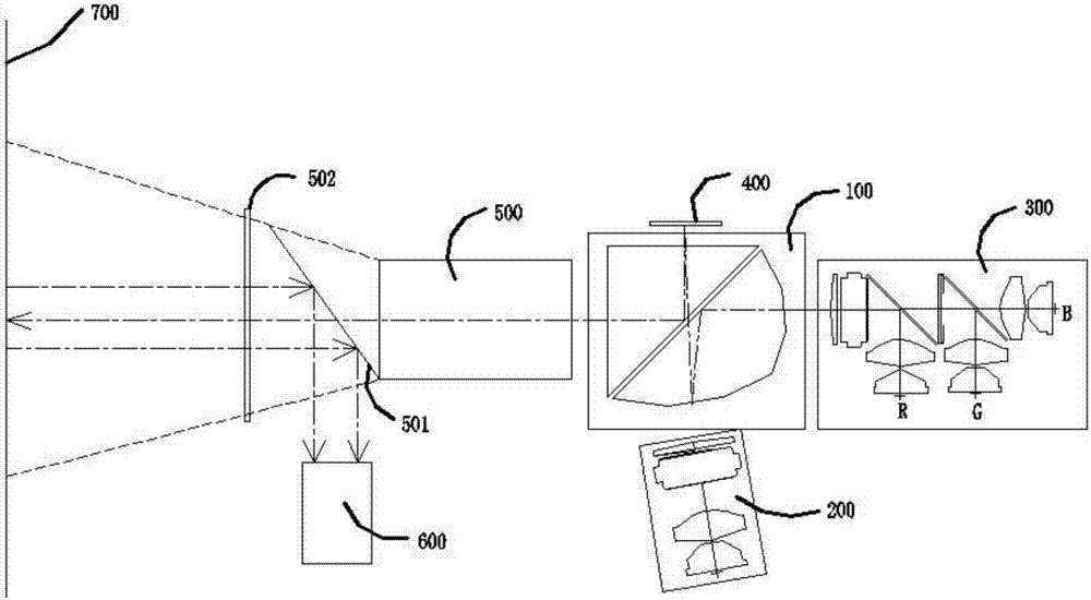
[0026] Such as figure 1 Shown is a schematic structural diagram of the infrared projection system of the present invention, including a projection module for generating interactive images and infrared light, a camera module 600 for sequentially acquiring interactive images and infrared light projected by the projection module, and a camera module for projecting interactive images and the projection area 700 of infrared light, the projection module and the camera module 600 of this embodiment are a module, which means that each component is packaged in a whole. Wherein, the projection module includes: an LED light source unit 300 for generating RGB three primary colors, an infrared light source unit 200 for generating infrared light, a light combining unit 100 for combining the light sources emitted by the LED light source unit 300 and the infrared light source unit 200, and generating a projection An image display unit 400 for an image and a lens 500 for receiving an image ref...

Embodiment 2

[0044] Such as Figure 5 Shown is a schematic structural diagram of the infrared projection system of this embodiment. The difference from Embodiment 1 is that the filter unit in this embodiment is set as a filter prism assembly 503 instead of the filter assembly 501. The filter The optical prism assembly 503 is bonded by two right-angle prisms. The bonding surface of the optical filter prism assembly 503 is located in front of the outgoing light path of the lens 500 and is at 45 degrees to the light exit surface of the lens 500. This optical filter prism assembly 503 can be a PBS The (Polarization BeamSplitter) prism can also be coated with a filter film that can transmit visible light and reflect infrared light reflected in the projection area twice at the rectangular prism bonding place 510 or be coated with a polarizing film that has a polarizing effect on infrared light. Wherein, the second wave plate 511 is arranged in front of the filter prism assembly 503 to improve th...

Embodiment 3

[0046] Such as Figure 6 , Figure 7 Shown is a schematic structural diagram of the infrared projection system of this embodiment. The difference between this embodiment and Embodiment 1 is that, as Figure 6 The projection module 601 completely retains the structure of the projection module in Embodiment 1, but as Figure 7 As shown, the camera module 602 is installed externally, so that the filter assembly 501 and the first wave plate 502 in the first embodiment are omitted, and the projection area 701 is still reserved. The light reflected by the projection area 701 can directly enter the camera module 602 without being reflected and filtered by the light filter assembly 501 and the first wave plate 502 , and the structure is simpler.


PUM


Abstract

An infrared projection system disclosed by the present invention comprises a projection module used for generating an interactive image and the infrared light; a shooting module used for obtaining the interactive image and the infrared light projected by the projection module orderly; and a projection area used for projecting the interactive image and the infrared light. The projection module comprises an LED light source unit, an infrared light source unit; a light synthesizing unit used for synthesizing the light sources emitted by the LED light source unit and the infrared light source unit; an image display unit used for generating a projection image; and a lens used for receiving the image coming from the image display unit and reflected by the light synthesizing unit. The light synthesizing unit comprises a prism group and a lens group which are used to transmit and reflect the light sources emitted by the LED light source unit and the infrared light source unit and irradiate to the image display unit to converge. The present invention provides the simplified projection system which integrates the projection image and the infrared light together and synthesizes the LED light source and the infrared light source, so that an infrared device is not arranged additionally, and the man-machine interactive operation is realized.

Description

technical field [0001] The invention relates to the field of projection display technology and human-computer interaction, in particular to an infrared projection system. Background technique [0002] Most of the current miniature projection light machines adopt the DLP technology of Texas Instruments, and its main image and light control devices are generally called DMD light modulators. It is a micro-mirror array with extremely high reflectivity. It needs to cooperate with the illumination optical system and the projection optical system to convert the commonly used RGB three primary colors into a projection image that is easy to see for our eyes. One of the commonly used methods of combining the illumination optical system and the projection optical system is to use a total internal reflection element having a lens surface. [0003] The current common human-computer interaction implementation scheme is to use an ordinary incandescent light source projector to project ima...

Claims


Application Information

Patent Timeline
IPC IPC(8): G03B21/14G03B21/20G06F3/01
CPCG03B21/14G03B21/20G06F3/017
Inventor 高志强杨伟樑赵远宁曼莹
Owner IVIEW DISPLAY SHENZHEN CO LTD
Why Eureka
Try Eureka