Cooperative transmission routing method for wireless sensor network based on multi-relay multi-hop

A wireless sensor and network collaboration technology, applied in wireless communication, advanced technology, electrical components, etc., can solve problems such as unsatisfactory energy saving effect, and achieve the effect of alleviating excessive energy consumption and avoiding waste of resources

Active Publication Date: 2017-07-28
JIANGSU COMSOFT TECH
5 Cites 16 Cited by

AI-Extracted Technical Summary

Problems solved by technology

[0005] The purpose of the present invention is to provide a cooperative transmission route for wireless sensor networks based on multiple relays and multiple hops to solve the defect that only multiple single-hop relays are considered in the existing cooperative transmission technology, resulting in unsatisfact...

Abstract

The invention discloses a cooperative transmission routing method for a wireless sensor network based on multi-relay multi-hop. The method comprises the following steps: step 1, a network initialization phase; step 2, a data preparation phase; step 3, a relay node number selection phase; and step 4, a data transmission phase. According to the cooperative transmission routing method for the wireless sensor network based on multi-relay multi-hop, a normal node in the sensor network sends the received data to an aggregation node at minimum transmission power through a multi-relay multi-hop transmission mode; and the minimum transmission power is calculated through the given interruption probability, and the optimal number of relay links and the optimal number of relay hops on each link can also be determined. By adopting the method, the resource waste caused by the excessive transmission power of source nodes or the occurrence of interruption caused by too low transmission power can be effectively avoided; the phenomenon that the number of relay links and the number of hops with minimum energy consumption can be found under different transmission distances can be ensured, and the problem of too fast energy consumption can be effectively alleviated.

Application Domain

Technology Topic

Data transmissionData preparation +10

Image

  • Cooperative transmission routing method for wireless sensor network based on multi-relay multi-hop
  • Cooperative transmission routing method for wireless sensor network based on multi-relay multi-hop
  • Cooperative transmission routing method for wireless sensor network based on multi-relay multi-hop

Examples

  • Experimental program(1)

Example Embodiment

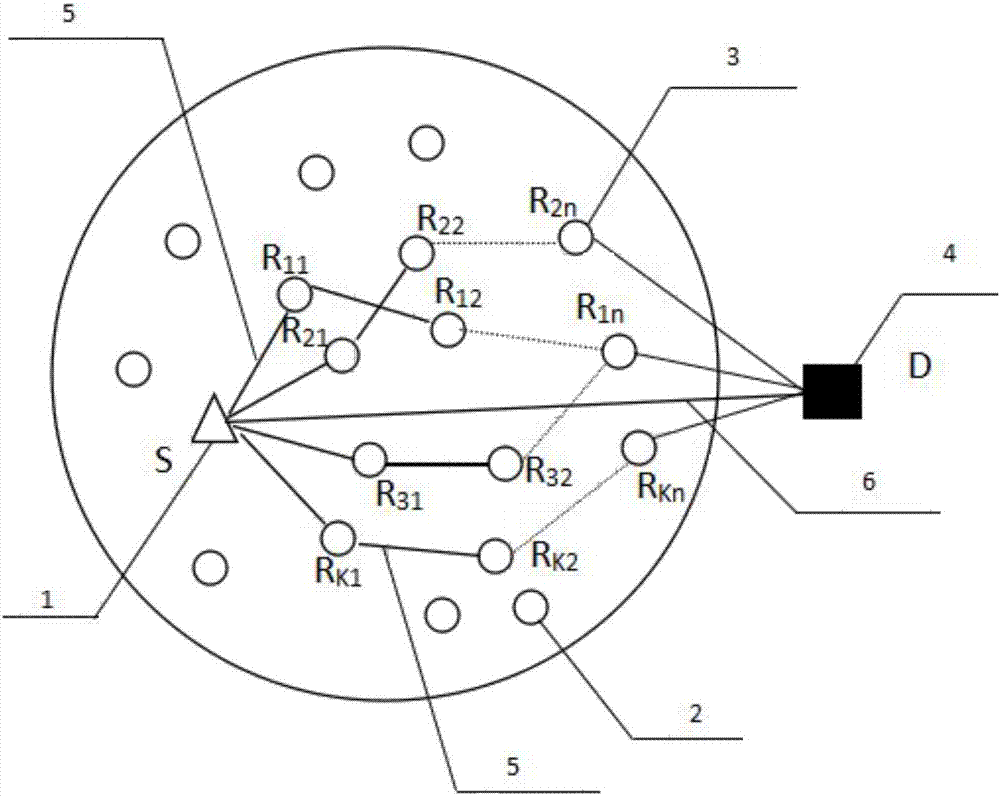
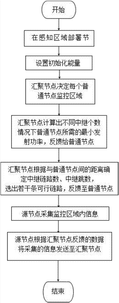
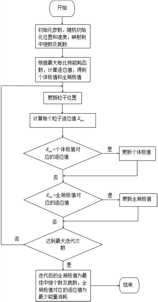
[0052] The present invention proposes a multi-relay and multi-hop cooperative transmission scheme that minimizes transmission power and optimizes the number of relay links and the number of relay hops on each link. The basis of the criteria can effectively calculate the minimum transmission power that meets the transmission stability in the entire network, and ensure that the number of relay links and hops that minimize energy consumption can be found under different transmission distances, effectively alleviating excessive energy consumption The problem. Its specific implementation is as follows:
[0053] The present invention is applicable to a large-scale wireless sensor network, the network includes a plurality of common nodes and a converging node; the relay node is generated from the common nodes; the function of any common node is to complete data collection and forward the data to the selected relay The node transmits data to the sink node through the relay node.
[0054] like figure 1 As shown, the wireless sensor network includes a source node 1, that is, an ordinary node that needs to transmit detected data to a sink node; an ordinary node 2; a selected relay node 3; a sink node 4; K serial links 5 for data transmission to the sink node 4; direct transmission link 6 between the source node 1 and the sink node 4.
[0055] The wireless sensor network cooperative transmission routing method based on multi-relay and multi-hop of the present invention comprises the following steps:
[0056] 1. Network initialization phase
[0057] Randomly deploy N (N>0) ordinary nodes with the same initial energy in the monitoring area, and the sink nodes are deployed anywhere around the network. All ordinary nodes send their own energy information and location information to the sink node, and the sink node determines the area monitored by each node according to the energy size and location information of the ordinary nodes.
[0058] 2. Data preparation stage
[0059] The sink node calculates the minimum transmit power required by common nodes under the condition of different numbers of relay nodes according to the following method, and feeds back these data to common nodes.
[0060] The minimum transmit power required by common nodes is calculated as follows:
[0061] The minimum transmit power of a common node is determined by its distance from the sink node and the probability of interruption during transmission. When the signal-to-noise ratio (SNR) at the receiving end falls below a threshold β that allows decoding errors, an interrupt will be generated. in R S (R S0) is the transmission rate. In order to ensure that the transmission performance reaches a standard, U represents the reliability of the relevant link, and the highest interruption probability is defined as: p out ≤1-U. Where U∈[0,1], generally U≥0.9.
[0062] like figure 1 As shown, there are K (K≥0) links in total, when the ith (i=1,2,...,K) optional link every two nodes S→R i,1 , R i,1 →R i,2 ,...,R i,j →R i,j+1 ,...,R i,n-1 →R i,n , R i,n → If all the data transmission between D is successful, it is considered that the i-th link is successfully transmitted, otherwise, it is considered to be interrupted. Among them, S represents the source node, that is, an ordinary node that needs to transmit the detected data to the sink node; D represents the sink node; j represents the number of relay hops on each hop link (j=1,2,...,n; n≥0), at this time, the i-th link outage probability is Π denotes the product sign. The entire network is composed of a direct transmission link between S and D and K relay links, and the data transmission failure of the direct transmission link between S and D and the K relay links will be interrupted. That is, the outage probability of the entire network can be expressed as
[0063] In this transmission scheme, the outage probability between any two nodes i, j can be expressed as:
[0064]
[0065] Among them, d i,j is the distance between node i and node j; α is the path loss index, which can be 1 to 5; h i,j Be the channel between i and j nodes, specifically refer to the Rayleigh fading channel in the present invention; N 0 is the noise power spectral density; P i,j The power required to transmit information from node i to node j.
[0066] The power required by any node i to send data to an adjacent node j depends on the distance between the two nodes and the path fading index α, if the distance between the source node and the sink node d S,D Known, then the power P sent by node i to node j i,j with P S,D The relationship is
[0067]
[0068] At this time, the transmit power of the source node can be determined by the outage probability and transmit power between any two adjacent nodes i and j above, as shown in the following formula:
[0069]
[0070] 3. The selection stage of the number of relay nodes
[0071] The number of relay nodes is determined according to the distance between common nodes and sink nodes. The aggregation node calculates the reasonable number of relay links and hops according to the energy consumption per bit of the multi-relay multi-hop scheme, selects a set of feasible links, and feeds back to the common nodes. The energy consumption per bit of the multi-relay multi-hop scheme can be expressed as:
[0072]
[0073] Among them, P AM =η×P S,D is the energy consumption of the power amplifier, which depends on the energy conversion efficiency η of the amplifier and the transmit power P S,D; b =R S B is the bit rate b/s. Optimize E by continuously adjusting K,n b , at this time, the K,n that makes it reach the minimum value is the final optimal number of links and hops required. The minimum value of K and n can be obtained through various optimization algorithms, such as particle swarm optimization algorithm, artificial fish swarm algorithm, genetic algorithm, simulated annealing algorithm, etc.
[0074] This embodiment solves the link number K and the hop number n of the relay based on the heuristic optimization algorithm. As a better implementation method, the present invention solves K and n based on the standard particle swarm optimization method in the heuristic optimization algorithm.
[0075] 1. Randomly generate M particles (M≥N). Initialize the particle velocity v K (t), v n (t) is a set of random numbers, initialize the values ​​of K and n to a set of random positive integers (K×n≤N-1), and map this value to the initial position of the particle x K (t),x n (t).
[0076] 2. Calculate the minimum transmit power P of the source node S,D.
[0077]
[0078] 3. Calculate the fitness function of each particle m(m∈M).
[0079]
[0080] Find the smallest E among them bmThe value of , save the corresponding relay link number K and relay node hop number n as the optimized position value.
[0081] 4. Update Particle Swarm
[0082] a. If the fitness value of the current particle is better than the fitness value of the particle at the previous moment, then update the individual extremum x of the current particle lopt ,
[0083] b. If the current particle fitness value is better than the global optimal fitness value at the last moment, update the current global extremum x gopt ,
[0084] c. Update the velocity v of each particle in the following formula K (t), v n (t) and position x K (t),x n (t).
[0085]
[0086]
[0087] x K (t)=x K (t-1)+v K (t)
[0088] x n (t)=x n (t-1)+v n (t)
[0089] Among them, w∈[0,1] is the inertia weight; r 1 and r 2 is a random number between [0,1], these two parameters are used to maintain the diversity of the group; the learning factor c 1 and c 2 is a non-negative constant, which enables the particle to have the ability to self-summarize and learn from outstanding individuals in the group, so as to approach its own historical optimal point and the historical optimal point within the group.
[0090] 5. Repeat steps 2-4 until the maximum number of iterations is reached.
[0091] 6. When the maximum number of iterations is reached, map the global optimal particle position to the optimal relay link number K and the optimal hop number n of each hop link. Corresponding E bm is the required minimum energy consumption value.
[0092] 4. Data transmission stage
[0093] The source node transmits data to the sink node via optimized K relay links with n hops.
[0094] The transmit power of WSN signals is calculated according to the probability of interruption during transmission. To a large extent, the energy consumption of the network depends on the reliability of the transmission process and the success rate of data transmission. The more data successfully transmitted, the more energy consumption is required. When the signal-to-noise ratio at the receiving end falls below a threshold that allows decoding errors, an interrupt will be generated. According to the outage probability of multi-relay and multi-hop, the transmission power of the cluster head node is calculated, which avoids the interruption caused by too low power, and avoids the waste of resources caused by too high power. The invention calculates the number of relay links and the number of relay hops of each link under the condition of the lowest energy consumption by using the particle swarm optimization algorithm, thereby avoiding the increase of energy consumption caused by too many or too few relay nodes.

PUM

no PUM

Description & Claims & Application Information

We can also present the details of the Description, Claims and Application information to help users get a comprehensive understanding of the technical details of the patent, such as background art, summary of invention, brief description of drawings, description of embodiments, and other original content. On the other hand, users can also determine the specific scope of protection of the technology through the list of claims; as well as understand the changes in the life cycle of the technology with the presentation of the patent timeline. Login to view more.

Similar technology patents

Classification and recommendation of technical efficacy words

Why Eureka
Try Eureka