
Diagnosis apparatus and method for detecting a defect of at least one of a plurality of light emitting diodes

A technology of light-emitting diodes and diagnostic devices, which is applied in the direction of testing electrical devices in transportation, diode testing, electroluminescent light sources, etc., and can solve problems such as large wiring costs

Active Publication Date: 2017-07-28
CONTINENTAL AUTOMOTIVE TECH GMBH
View PDF9 Cites 1 Cited by
  • Summary
  • Abstract
  • Description
  • Claims
  • Application Information

AI Technical Summary

Problems solved by technology

The disadvantage of this solution is that high wiring costs arise, since each LED must be connected in parallel with its own detection circuit

Method used


Image

  • Diagnosis apparatus and method for detecting a defect of at least one of a plurality of light emitting diodes
  • Diagnosis apparatus and method for detecting a defect of at least one of a plurality of light emitting diodes

Examples


Embodiment Construction

[0032] The examples described below are preferred embodiments of the present invention. In this example, the described components of this embodiment are individual features of the invention to be considered independently of each other, which also respectively improve the invention independently of each other, and which in turn can also be used individually or in the same manner as shown Different combinations are considered as part of the invention. Furthermore, the described embodiments can also be supplemented by other features of the invention that have already been described.

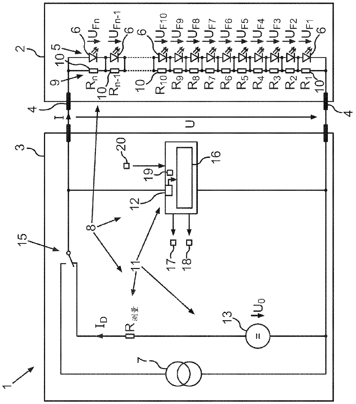
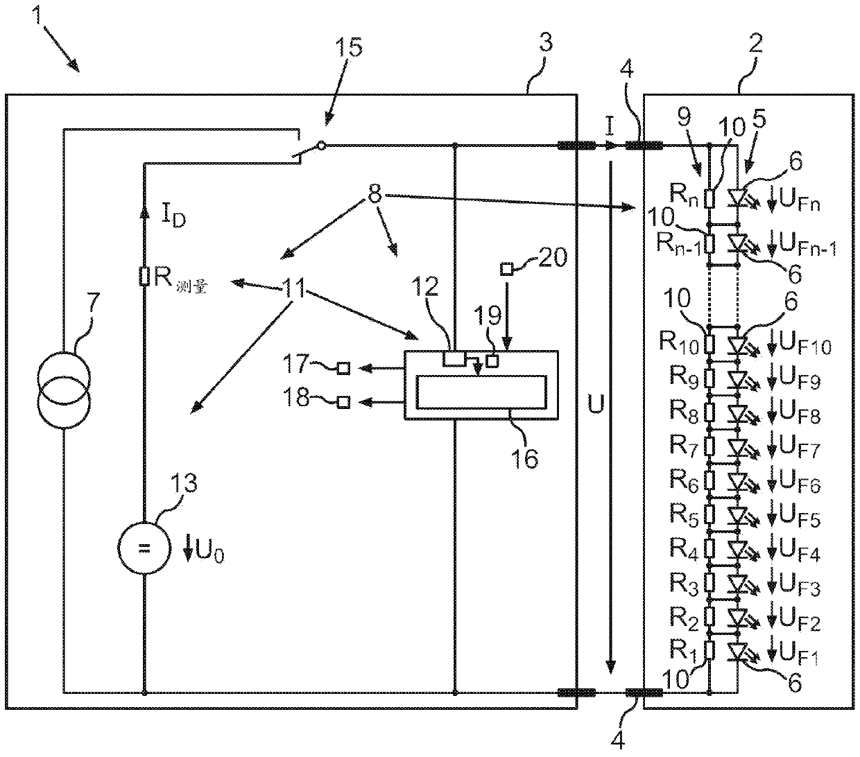
[0033] figure 1 Shown is a lighting device 1 which can be designed, for example, as a motor vehicle headlight. An LED lighting device 2 and an LED controller 3 are shown. The LED lighting device 2 is electrically connected to the LED controller 3 through two power supply connectors 4 . In the LED luminous means 2 , a light-emitting diode row 5 consisting of light-emitting diodes 6 is inserted be...


PUM


Abstract

The invention relates to a diagnosis apparatus (8) for detecting a defect of at least one of a plurality of light emitting diodes (6) which are interconnected to form a light emitting diode series (5) connecting a first supply terminal (4) to a second supply terminal (4). The defect is intended to be detected with little wiring outlay. The invention provides that a resistance element (10) is connected in parallel with each light emitting diode (6) and a measuring device (11) is configured to generate a diagnosis current (ID) between the two supply terminals (4) in a luminous pause, during which none of the light emitting diodes (6) emit light, said diagnosis current giving rise, at each resistance element (10), to a voltage lower than a forward voltage (UF), starting from which the light emitting diode (6) respectively connected in parallel emits light, and to provide a voltage value (19) of a diagnosis voltage (U) dropped between the supply terminals (4).

Description

technical field [0001] The invention relates to a diagnostic device and a method for detecting defects in at least one of a plurality of light-emitting diodes which are connected to form a light-emitting diode row, via which two power supply connections are connected to one another. The row of light-emitting diodes can be provided in particular in a motor vehicle headlight. However, the light-emitting diode row can also be part of a domestic lighting system or part of another lighting device. Background technique [0002] It is common in an LED light emitting device (LED-Light Emitting Diode, light emitting diode) that each light emitting diode is connected in series to form an LED string or a column of light emitting diodes, and is powered from a current source. A single light-emitting diode row can hereby be formed from more than 10 individual light-emitting diodes connected in series. An LED column usually has only two power supply connections to allow the current from ...

Claims


Application Information

Patent Timeline
IPC IPC(8): H05B33/08B60Q11/00H05B44/00
CPCB60Q11/005H05B45/54G01R31/44G01R31/006H05B45/58H05B45/395Y02B20/30B60Q1/04G01R31/2635
Inventor W.克尔纳M.奥斯迪厄P.布赖卡
Owner CONTINENTAL AUTOMOTIVE TECH GMBH
Learn More