
Standard hole machining device for bathtub

A processing device and standard hole technology, applied in the direction of metal processing equipment, metal processing machinery parts, manufacturing tools, etc., can solve problems such as poor quality, difficulty in ensuring the position and size of holes, and non-standard drilled holes

Inactive Publication Date: 2017-08-01
CHENGDU TAOMASI BATHROOM
View PDF9 Cites 0 Cited by
  • Summary
  • Abstract
  • Description
  • Claims
  • Application Information

AI Technical Summary

Problems solved by technology

[0004] The technical problem to be solved by the present invention is that the holes drilled by manual drilling are not standard, and the purpose is to provide a standard hole processing device for bathtubs, so as to solve the problem that it is difficult to ensure the position of the holes and the location of the holes in the case of low cost. The size of the drilled hole is not standard, the quality is poor and the problem does not meet the requirements

Method used


Image

  • Standard hole machining device for bathtub

Examples


Embodiment 1

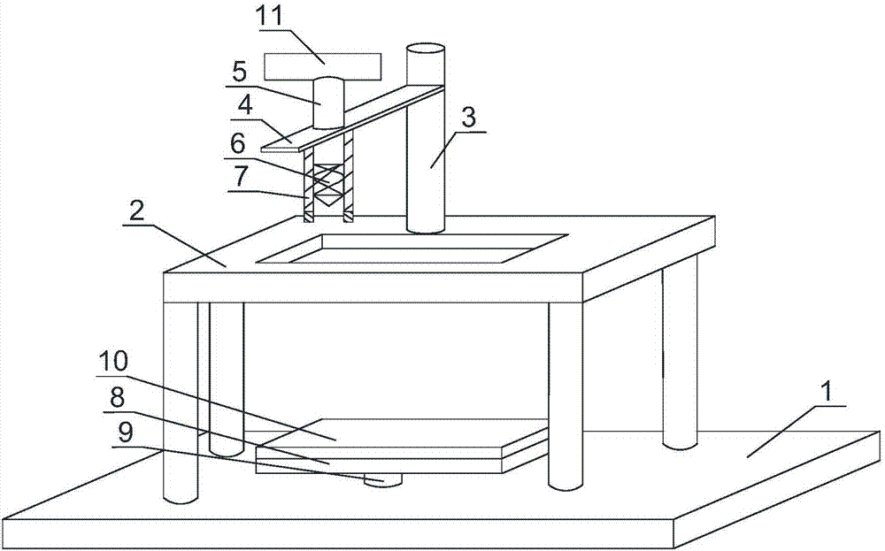
[0022] Such as figure 1 As shown, the standard hole processing device for bathtubs of the present invention includes a base 1, a workbench 2 is connected above the base 1, and a through groove 3 for placing workpieces is arranged on the workbench 2, and one side of the through groove 3 A drilling tool and a fixing frame for fixing the drilling tool are arranged on the workbench 2 of the working table, and the fixing frame includes a telescopic column 3 vertically installed on the workbench 2, and the top of the telescopic column 3 is connected with a telescopic rod 4, and the telescopic rod 4 Horizontally installed, the end of the telescopic rod 4 away from the telescopic column 3 is provided with a through hole for the insertion of the drilling tool. Twist drill bit 6 is arranged, and the bottom of expansion rod 4 is provided with sleeve pipe 7 with buffer pad, and described sleeve pipe 7 is sleeved outside drill pipe 5 and is tangent to drill pipe 5 . A swivel for the teles...

Embodiment 2

[0025] Based on Embodiment 1, the base 1 below the through groove 3 is provided with a placement platform 8 for placing workpieces, the placement platform 8 is connected to the base 1 through a hydraulic column 9, and when the placement platform 8 is connected to the through groove 3, the placement platform 8 is inscribed with through groove 3. The upper surface of the placing table 8 is covered with a rubber pad 10 .

[0026] The placing table is used to place the bathtub, which plays a role of fixing and strengthening the bathtub; when it is not working, the placing table is at the bottom of the base, which is convenient for placing the bathtub. After the bathtub is placed, the placing table can be raised by the hydraulic column, and the placing table rises to It can be stopped inside the through groove; on the one hand, the rubber pad can fix the bathtub to prevent the bathtub from sliding on the placing table and affect the quality of drilling, on the other hand, it can ac...


PUM


Abstract

The invention discloses a standard hole machining device for a bathtub. The standard hole machining device comprises a base. The upper portion of the base is connected with a workbench. A through groove for containing a workpiece is formed in the workbench. A drilling tool and a fixing frame for fixing the drilling tool are arranged at the position, on one side of the through groove, of the workbench. The fixing frame comprises a telescopic column vertically mounted on the workbench. The top of the telescopic column is connected with a telescopic rod. The telescopic rod is horizontally mounted. A through hole allowing the drilling tool to be inserted therein is formed in the end, away from the telescopic column, of the telescopic rod. The drilling tool comprises a drilling rod with the front end downwards penetrating the through hole to the position below the telescopic rod. An auger bit is mounted at the front end of the drilling rod. A casing pipe with a buffer pad arranged at the bottom is mounted below the telescopic rod. The casing pipe is connected to the outer portion of the drilling rod in a sleeving manner and is tangent to the drilling rod. According to the standard hole machining device, it is guaranteed that the quality of a machined hole meets the requirement by determining the position of the bit.

Description

technical field [0001] The invention relates to a punching device, in particular to a standard hole processing device for a bathtub. Background technique [0002] The acrylic bathtub is a bathtub made of a PMMA plastic material. The acrylic bathtub body is composed of a surface layer (acrylic layer) and an inner layer (glass fiber resin reinforcement layer). It is characterized by rich shapes, light weight, good surface finish, and low price; at present, acrylic bathtub bottles have become one of the highest-selling bathtubs on the market due to their advantages. [0003] In the production and processing of acrylic bathtubs, after the acrylic bathtub is integrally formed, most of them need to be drilled on the acrylic bathtub, and it is difficult to master the drilling of acrylic bathtubs. The position and size of the hole may also cause hole collapse or damage to the acrylic plate. Contents of the invention [0004] The technical problem to be solved by the present inve...

Claims


Application Information

Patent Timeline
Patent Type & Authority Applications(China)
IPC IPC(8): B23B41/00B23Q11/00
CPCB23B41/00B23Q11/00
Inventor 刘开亮
Owner CHENGDU TAOMASI BATHROOM
Learn More