Liquid jet head, liquid jet recording device, and method of manufacturing liquid jet head
A liquid ejection head, liquid technology, applied in printing and other directions, can solve problems such as water repellent film peeling
- Summary
- Abstract
- Description
- Claims
- Application Information
AI Technical Summary
Problems solved by technology
Method used
Image

Examples
no. 1 approach
[0057] (Liquid jet recording device)
[0058] figure 1 It is a perspective view of the liquid jet recording device 1 .
[0059] The liquid jet recording device 1 is a so-called inkjet printer, and includes a pair of transport mechanisms 2 and 3 for transporting a recording medium S such as paper, a liquid jet head 4 for jetting ink droplets to the recording medium S, and a liquid jet head 4 that supplies ink droplets. A liquid supply unit 5 for ink, and a scanning unit 6 for scanning the liquid jet head 4 in a direction (sub-scanning direction) substantially perpendicular to the conveyance direction of the recording medium S (main scanning direction).
[0060] In addition, in the drawings used in the following description, the scale of each member is appropriately changed in order to make each member a recognizable size.
[0061] In addition, in the following description, the sub-scanning direction is referred to as the X direction, the main scanning direction is referred to...
no. 2 approach
[0142] Figure 12 is an enlarged cross-sectional view of main parts of the nozzle guard 201 in the second embodiment, and the above-mentioned Image 6 correspond.
[0143] In addition, the nozzle guard 201 is formed of, for example, a stainless steel plate with a thickness of about 0.3 mm, a frame body 202 formed in the shape of a picture frame, and a cover that is formed separately from the frame body 202 and closes the lower opening 202a. The basic configuration such as the point that the body 203 is integrated is the same as that of the nozzle guard 101 of the first embodiment described above (the same applies to the following embodiments).
[0144] Here, in the inner flange portion 204a formed by the frame body 202 of the nozzle guard 201 in the second embodiment, a picture frame-shaped joint flange portion 222 is integrally formed on the inner periphery so as to protrude toward the inner peripheral side. side nozzle plate 35 (in Figure 12 (not shown in the figure) sid...
no. 3 approach
[0152] Figure 13 is an enlarged sectional view of main parts of the nozzle guard 301 in the third embodiment, and Image 6 correspond. In addition, in 3rd Embodiment, the same code|symbol is attached|subjected to the same form as said 1st Embodiment, and description is abbreviate|omitted.
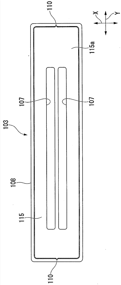
[0153] Here, in the third embodiment, the surface of the outer flange portion 108 on the side where the step is formed (the surface on the back surface 115 a side of the cover body 115 ) is set from above in the Z direction ( Figure 13 The lower part of the frame body 102 overlaps with the inner flange part 104a of the frame body 102 . This point is different from the first embodiment described above. In this case, the back surface 115a of the cover body 115 faces downward in the Z direction ( Figure 13 above in).
[0154] In the case of such a configuration, it is also possible to make the cover 103 and the nozzle plate 35 (in Figure 13 not shown in ) fit snugly.
[0155] In add...
PUM
 Abstract
Description
Claims
Application Information
 - R&D
- Intellectual Property
- Life Sciences
- Materials
- Tech Scout
- Unparalleled Data Quality
- Higher Quality Content
- 60% Fewer Hallucinations
Browse by: Latest US Patents, China's latest patents, Technical Efficacy Thesaurus, Application Domain, Technology Topic, Popular Technical Reports.
© 2025 PatSnap. All rights reserved.Legal|Privacy policy|Modern Slavery Act Transparency Statement|Sitemap|About US| Contact US: help@patsnap.com