Confluence mechanism

A technology of convex rails and rollers, which is applied to conveyors, conveyor objects, mechanical conveyors, etc., can solve problems such as hanger jamming, high error rate, and hanger drop, so as to improve processing efficiency, reduce processing difficulty, and have a simple structure. Effect

Active Publication Date: 2017-08-01
NINGBO SUNRISE IND AUTOMATION CO LTD +1
View PDF10 Cites 3 Cited by
  • Summary
  • Abstract
  • Description
  • Claims
  • Application Information

AI Technical Summary

Problems solved by technology

There are two commonly used methods now: one is manual, with low efficiency and high error rate; the other is the processing method of multi-branch rails, which is to put different materials into different branch rails of the same workstation, and then pass the confluence between the branch rails. Convey the same set of materials to the processing position
Although the efficiency and error rate of this method have been improved, but because the confluence structure is too simple, the branch rail is a circular structure, without any protection measures, and the hangers often get stuck and fall off, which is difficult to meet the use requirements

Method used


Image

  • Confluence mechanism
  • Confluence mechanism
  • Confluence mechanism

Examples


Embodiment Construction

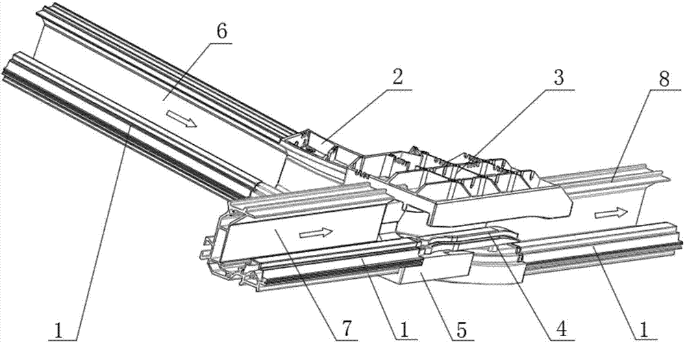
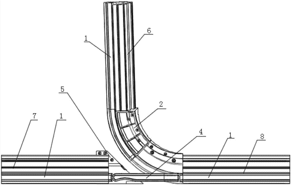
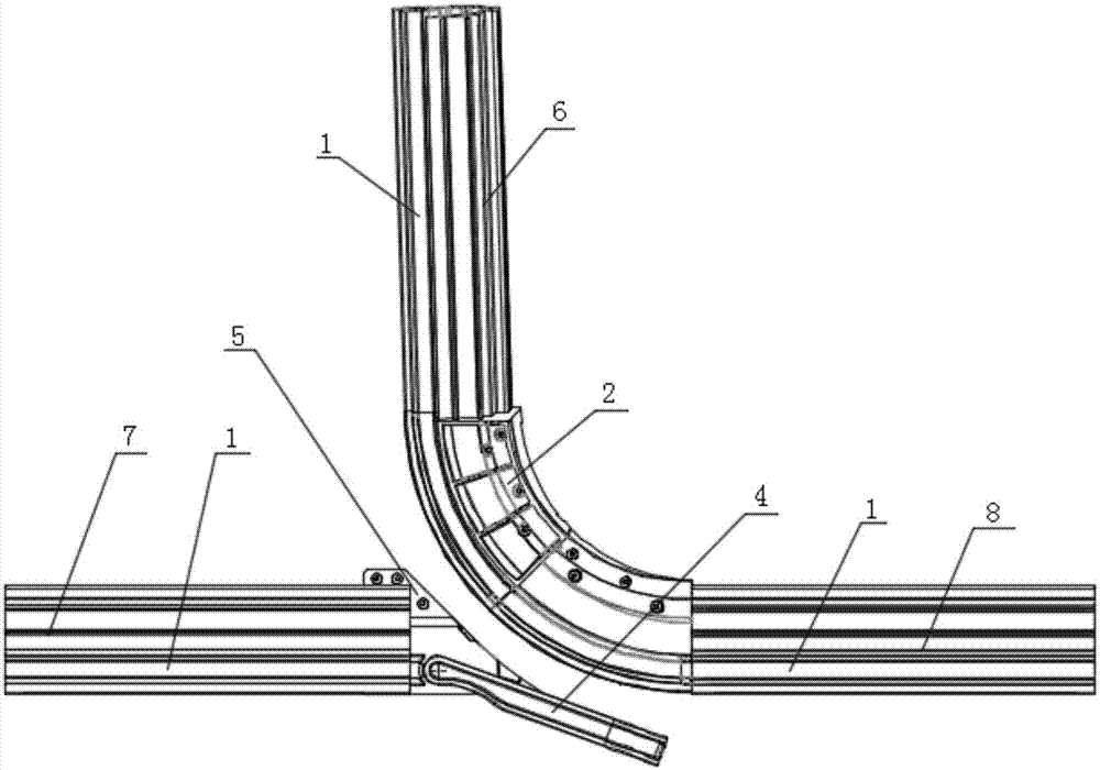
[0019] Such as Figure 1-6 As shown, the merging mechanism provided by the present invention includes a first branch rail 6 , a second branch rail 7 , and a merging rail 8 . The outlet end of the first branch rail 6 is connected with the inlet end of the confluence rail 8 , and the outlet end of the first branch rail 6 can also be connected with the inlet end of the confluence rail 8 through the elbow seat 2 . The second branch rail 7 and the confluence rail 8 are on the same straight line, and there is a gap between the second branch rail 7 and the confluence rail 8 . The bottoms of the first branch rail 6, the second branch rail 7, the confluence rail 8 and the elbow seat 2 are all provided with a roller hanger ledge 1, and the roller clothes hanger can roll on the roller hanger ledge 1. The first branch rail 6, the elbow seat 2, and the roller clothes hanger protruding rail 1 on the converging rail 8 are connected end to end successively to form a continuous protruding rai...


PUM


Abstract

The invention provides a confluence mechanism. The confluence mechanism is used for connecting tracks, and the tracks comprises a first branch track, a second branch track and a confluence track, wherein the outlet end of the first branch track is connected with the inlet end of the confluence track, the second branch track is disconnected with the confluence track, the first branch track, the second branch track and the confluence track are provided with roller hanger protruding tracks, and the roller hanger protruding track on the first branch track and the roller hanger protruding track on the confluence track are connected end to end to form a continuous protruding track; and a confluence mechanism comprises a fixing seat and a swing head, the fixing seat is arranged at the outlet end of the second branch track, one end of the swing head is rotatably arranged on the fixing seat, and the other end of the swing head can rotate to the position above the continuous protruding track. According to the confluence mechanism, the rotatable swing head is arranged at the outlet end of the second branch track, the confluence between the swing head and the first branch track can be realized, the structure is simple, and the maintenance is easy.

Description

technical field [0001] The invention relates to the technical field of suspension conveying systems, in particular to a confluence mechanism. Background technique [0002] At present, in the logistics conveyor line structure, especially in the clothing or home textile suspension conveyor line system, it is often required to sort and pair materials, so the materials need to be diverted and merged. There are two commonly used methods now: one is manual, with low efficiency and high error rate; the other is the processing method of multi-branch rails, which is to put different materials into different branch rails of the same workstation, and then pass the confluence between the branch rails. Convey the same set of materials to the processing position. Although the efficiency and error rate of this method have been improved, but because the confluence structure is too simple, the branch rail is a circular structure, without any protection measures, the hangers often get stuck ...

Claims


Application Information

Patent Timeline
Patent Type & Authority Applications(China)
IPC IPC(8): B65G35/00B65G47/68
CPCB65G35/00B65G47/68B65G2201/0229
Inventor 孙建国余云林袁峰
Owner NINGBO SUNRISE IND AUTOMATION CO LTD
Why Eureka
Try Eureka