Inner cooling circulation system structure for magnetic pump

A technology of circulation system and magnetic pump, which is applied to components, pumps, and pump components of elastic fluid pumping devices, and can solve problems such as heat removal, loss of magnetism of the internal magnetic rotor, and reduction of natural circulation capacity, etc., to achieve Improve anti-cavitation performance, improve flow capacity, and simple structure

Inactive Publication Date: 2017-08-01
DANDONG TOP PUMP
View PDF5 Cites 2 Cited by
  • Summary
  • Abstract
  • Description
  • Claims
  • Application Information

AI Technical Summary

Problems solved by technology

[0004] In the above-mentioned prior art, when the flow rate of the medium at the outlet of the pump chamber is too low and the flow rate is too slow, the natural circulation capacity of the internal cooling circulation system of the above-mentioned magnetic pump is greatly reduced, and the medium flow rate in the internal cooling circulation system of the magnetic pump is not enough for cooling. When the heat is taken away, it will cause the inner magnetic rotor to lose magnetism due to excessive temperature rise; at the same time, it will also cause the temperature of the sliding bearing to be too high
[0005] Moreover, when the temperature of the conveyed medium is high, the internal cooling circulation system of the magnetic pump cannot effectively remove heat, and it will further heat the isolation sleeve, internal magnetic rotor, ...

Method used


Image

  • Inner cooling circulation system structure for magnetic pump

Examples


Embodiment Construction

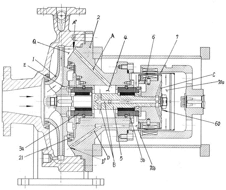
[0018] The structure of the internal cooling circulation system of the magnetic pump of the present invention is formed on the pump cover 2 by the high-pressure zone at the outlet of the impeller 1 corresponding to the pump cavity Q, and the liquid inlet hole A leading to the shaft cavity 4 between the left and right sliding bearings 3a, 3b, The liquid inlet hole B leading to the rear end of the main shaft 5 is opened on the main shaft 5 in the shaft cavity 4 between the left and right sliding bearings 3a, 3b, and the liquid inlet on the main shaft 5 is distributed radially on the rear end surface 60 of the inner magnetic rotor 6. The rear end of the hole B corresponds to the connected liquid inlet hole C, and the inclined radial liquid inlet hole C on the inner magnetic rotor (6) forms a centrifugal pump effect on the medium liquid, and the opening on the pump cover 2 corresponds to the outer side of the pump cover seal ring 21 The liquid outlet hole D leading to the inner cav...


PUM


Abstract

The invention provides an inner cooling circulation system structure for a magnetic pump. The inner cooling circulation system structure is characterized by being composed of a liquid inlet hole (A), a liquid inlet hole (B), a liquid inlet hole (C), a liquid outlet hole (D) and a pressure balance back flow hole (E), wherein the liquid inlet hole (A) is formed in a pump cover (2) and leads to a shaft cavity (4) between a left sliding bearing (3a) and a right sliding bearing (3b); the liquid inlet hole (B) is formed in a main shaft (5) and leads to the back end of the main shaft (5); the liquid inlet hole (C) is distributed and radially formed in the back end surface of an inner magnetic rotor (6) and communicates with the liquid inlet hole (B) in the main shaft; the liquid outlet hole (D) is formed in the pump cover (2) and leads to an isolation sleeve inner cavity (70b) on the front side of the inner magnetic rotor (6); the pressure balance back flow hole (E) is formed in an impeller (1); and a medium conducts centrifugal pump effect action when passing the liquid inlet hole (C) in the inner magnetic rotor (6), so that the flowing capacity of the cooling medium is promoted. The inner cooling circulation system structure for the magnetic pump is suitable for conveying easily-cavitated media, prevents the situation that heat of a magnetic vortex returns to an inlet of the impeller and produces steam explosion and cavitation phenomena, improves the anti-cavitation performance of the magnetic pump, and is more suitable for complicated working conditions.

Description

technical field [0001] The invention relates to a magnetic pump, in particular to the structure of the internal cooling circulation system of the magnetic pump. Background technique [0002] The internal cooling circulation system of the magnetic pump transports the medium in the pump chamber to the isolation sleeve as a circulating coolant to take away the heat from the isolation sleeve, front and rear thrust plates, and front and rear sliding bearings. The bearing acts as a lubricant. [0003] The internal cooling circulation system of the magnetic pump in the prior art consists of a liquid inlet hole leading to the inner cavity of the isolation sleeve opened on the pump cover corresponding to the high pressure area at the outlet of the impeller of the pump chamber, and a return hole opened in the center of the pump shaft. The pressure balance return hole opened at the root of the wall, the medium conveyed in the pump chamber enters the inner cavity of the isolation sleev...

Claims


Application Information

Patent Timeline
IPC IPC(8): F04D29/58
CPCF04D29/586
Inventor 刘义昕贺传斌张成东刘锋
Owner DANDONG TOP PUMP
Why Eureka
Try Eureka