Biomass pyrolysis gasification furnace of star composite structure

A combined structure, pyrolysis and gasification technology, applied in the direction of incinerators, coke ovens, combustion types, etc., can solve the problems of difficult to reach the pyrolysis temperature, complex furnace structure, large overall size, etc., to achieve sufficient pyrolysis, improve Pyrolysis efficiency, small overall size effect

Pending Publication Date: 2017-08-01
广东英翔科技有限公司
View PDF0 Cites 0 Cited by
  • Summary
  • Abstract
  • Description
  • Claims
  • Application Information

AI Technical Summary

Problems solved by technology

The price is that the structure of the furnace body is complex, the overall size is large, it is difficult to reach

Method used


Image

  • Biomass pyrolysis gasification furnace of star composite structure
  • Biomass pyrolysis gasification furnace of star composite structure

Examples


Example Embodiment

[0024] Example 1

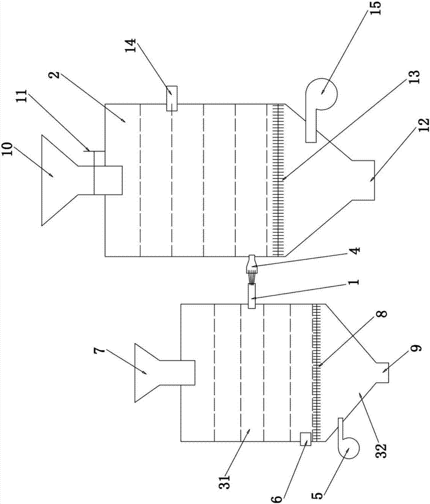
[0025] Such as figure 1 As shown, a biomass pyrolysis and gasification furnace with a star-shaped combined structure includes a main furnace 3, the main furnace 3 is correspondingly matched and connected with at least one auxiliary furnace 2, and at least one circle is provided on the main furnace 3 The tube connecting tube 1 is provided with a cone tube connecting tube 4 on the auxiliary furnace 2, and each cylindrical connecting tube 1 is matched and connected with a corresponding cone tube connecting tube 4. The star-shaped combination structure of the present invention The main furnace 3 in the biomass pyrolysis gasification furnace uses biomass energy blocks with high calorific value to produce combustible gas, and the flame generated is used to start a plurality of parallel auxiliary furnaces 2, so that the types of biomass raw materials in the auxiliary furnace 2 And the humidity is changed, it can process the biomass fuel with higher water content witho...

Example Embodiment

[0031] Example 2

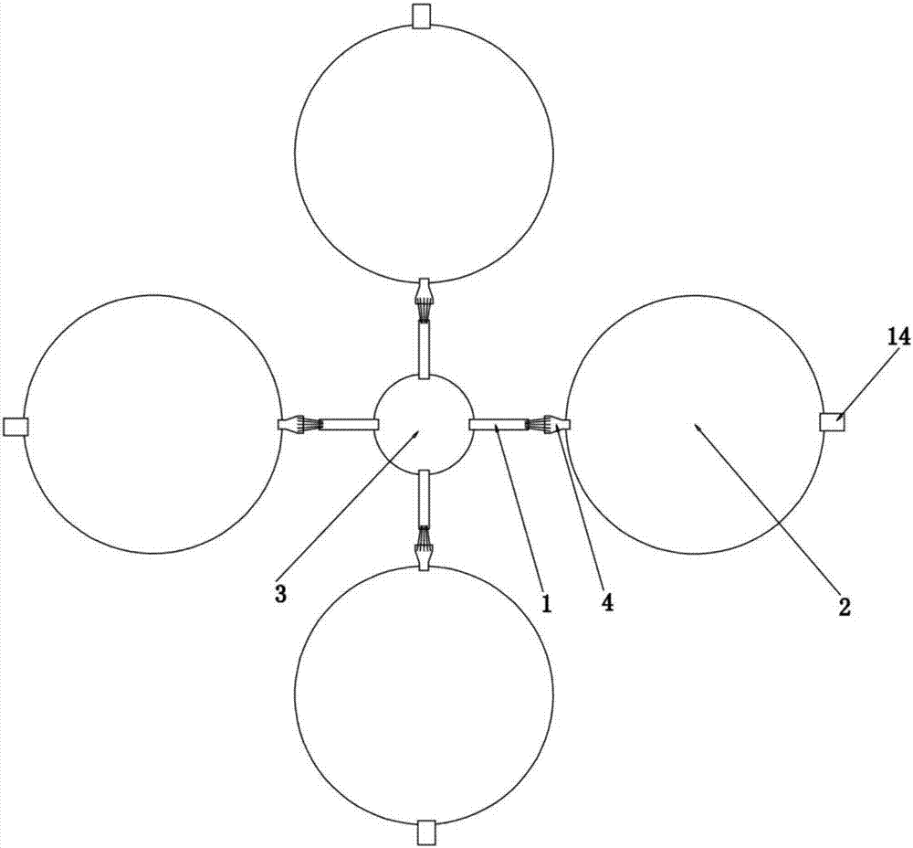
[0032] Such as figure 2 As shown, in this embodiment, the similarities with the first embodiment will not be repeated. The difference is that in this embodiment, a star-shaped biomass pyrolysis gasifier with a main furnace in parallel with four auxiliary furnaces is used. Mainly can process a large amount of biomass raw materials.

[0033] The present invention adopts a small-sized main furnace 3, and four relatively large-sized auxiliary furnaces 2 are connected by connecting pipes to form a pyrolysis and gasification furnace with a one-to-multiple star structure. The main furnace 3 is used to burn the high calorific value energy block to generate high-temperature gas, and then the combustible gas in the gap between the cylindrical connecting pipe 1 and the cone connecting pipe 4 is respectively ignited, thereby starting the auxiliary furnace 2 connected in the ring. According to the actual needs, the main furnace 3 and the auxiliary furnace 2 can be adjusted...


PUM


Abstract

The invention discloses a biomass pyrolysis gasification furnace of a star composite structure. The biomass pyrolysis gasification furnace comprises a main furnace. The main furnace is correspondingly and cooperatively connected with at least one auxiliary furnace. At least one cylinder connecting pipe is arranged on the main furnace. Each auxiliary furnace is provided with a cone connecting pipe. Each cylinder connecting pipe is correspondingly and cooperatively connected with the corresponding cone connecting pipe. A main furnace slag discharging opening is formed in the bottom of the main furnace, and a main furnace air blower is arranged above the main furnace slag discharging opening. A main furnace grate is arranged above the main furnace air blower, an ignition opening is formed above the main furnace grate, and a main furnace feeding hopper is arranged on the top of the main furnace. By means of the biomass pyrolysis gasification furnace of the star composite structure, the main furnace and the multiple auxiliary furnaces of the same structure are adopted, a furnace body combination of the star structure is achieved, the main furnace drags the several parallel auxiliary furnaces to achieve efficient pyrolysis, meanwhile, the main furnace and the auxiliary furnaces are all small in size, and therefore manufacturing, transporting, construction, installation and later-period maintenance cost is relatively low.

Description

technical field [0001] The invention relates to the field of gasifiers, in particular to a biomass pyrolysis gasifier with a star-shaped combined structure. Background technique [0002] At present, biomass pyrolysis and gasification technology mainly uses low-oxygen combustion of some biomass materials, and then uses the heat and residual oxygen of the flue gas to pyrolyze and gasify the rest of the biomass materials. The main structure is to use a single gasification furnace for upper feeding or side feeding, and the external high-temperature flue gas is injected into the furnace to achieve high-temperature pyrolysis of biomass and generate flammable gas. Usually this kind of gasification furnace is bulky and requires external heat supply, especially when the temperature in the furnace is unstable and cannot reach the stable pyrolysis temperature, an external heat source needs to be provided. [0003] There are mainly three types of gasifiers in the prior art, such as cyc...

Claims


Application Information

Patent Timeline
IPC IPC(8): F23G5/027F23G5/44C10B53/00C10B57/00
CPCF23G5/027C10B53/00C10B57/00F23G5/44
Inventor 关培声英志祥吴永明何有明
Owner 广东英翔科技有限公司
Why Eureka
Try Eureka