
Gas-liquid separator for plate-type evaporator and plate-type evaporator

A plate evaporator, gas-liquid separator technology, applied in evaporator/condenser, refrigeration and liquefaction, refrigeration components, etc. System cooling effect and other problems, to avoid the reduction of heat exchange efficiency, improve work reliability, and simple structure

Pending Publication Date: 2017-08-01
依米康冷元节能科技(上海)有限公司
View PDF11 Cites 1 Cited by
  • Summary
  • Abstract
  • Description
  • Claims
  • Application Information

AI Technical Summary

Problems solved by technology

[0004] However, the current refrigeration system often has the following disadvantages: the refrigerant after being depressurized by the throttling device is a gas-liquid two-phase, and the gas-liquid two-phase refrigerant flows into the plate evaporator at the same time, which will speed up the flow rate, and most of the liquid refrigerant is concentrated in the At the end of the inlet pipe of the plate evaporator, the gaseous refrigerant is concentrated at the front end of the inlet pipe. When the gaseous refrigerant flows through the evaporator, it will not only fail to achieve refrigeration, but also cause the liquid refrigerant to be distributed unevenly in the evaporator, reducing the temperature of the evaporator. The effective heat transfer area seriously affects the heat transfer efficiency of the plate evaporator, which in turn affects the cooling effect of the entire refrigeration system

Method used


Image

  • Gas-liquid separator for plate-type evaporator and plate-type evaporator
  • Gas-liquid separator for plate-type evaporator and plate-type evaporator
  • Gas-liquid separator for plate-type evaporator and plate-type evaporator

Examples


Embodiment Construction

[0028] The refrigerant in the refrigeration system is often a gas-liquid two-phase after being reduced by a throttling device. The gas-liquid two-phase refrigerant flowing into the plate evaporator at the same time will increase the flow rate, and most of the liquid refrigerant is concentrated in the plate evaporator inlet pipe At the end of the evaporator, the gaseous refrigerant is concentrated at the front end of the inlet pipe. When the gaseous refrigerant flows through the evaporator, it not only fails to achieve cooling, but also causes uneven distribution of the liquid refrigerant in the evaporator, reducing the effective heat exchange area of ​​the evaporator , Which seriously affects the heat exchange efficiency of the plate evaporator, and further affects the cooling effect of the entire refrigeration system.

[0029] In order to solve the above problems, this embodiment proposes a gas-liquid separator for a plate evaporator, which can separate the refrigerant after pass...


PUM


Abstract

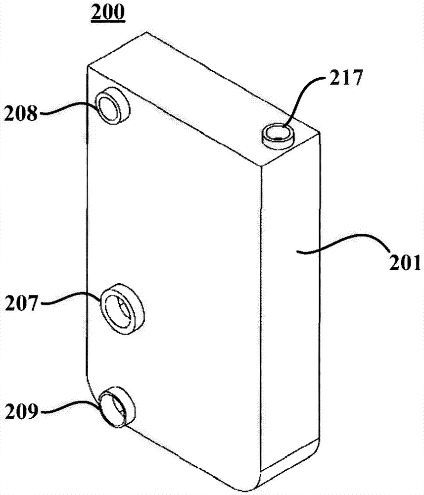
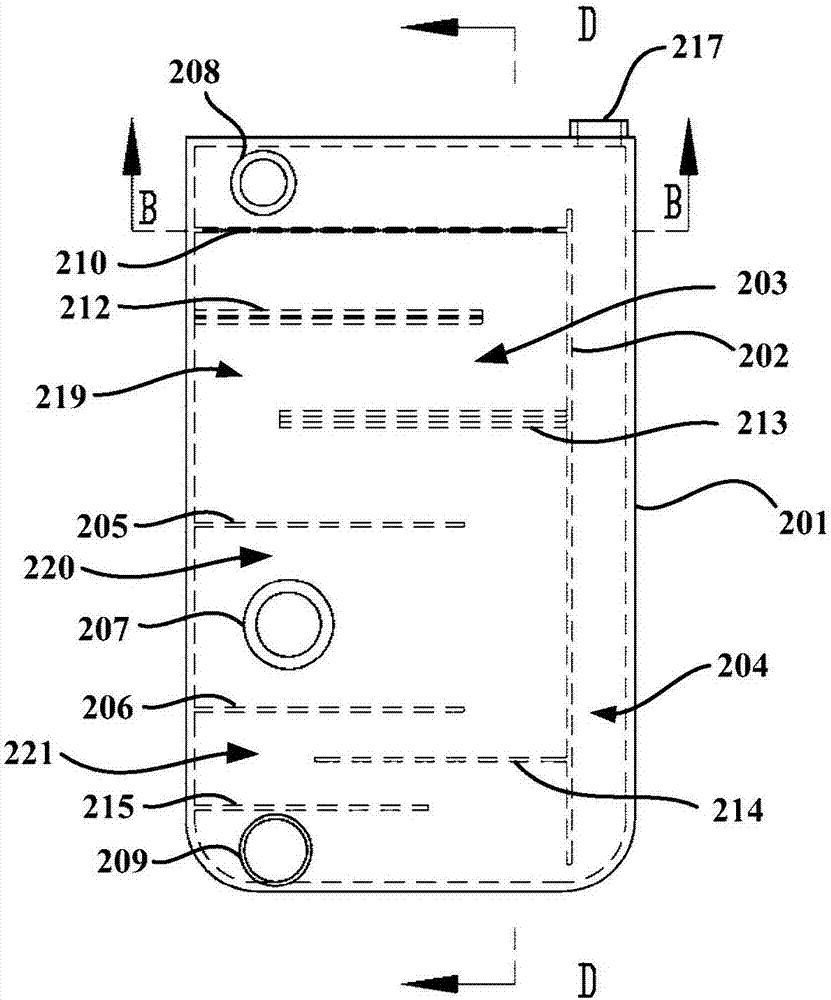
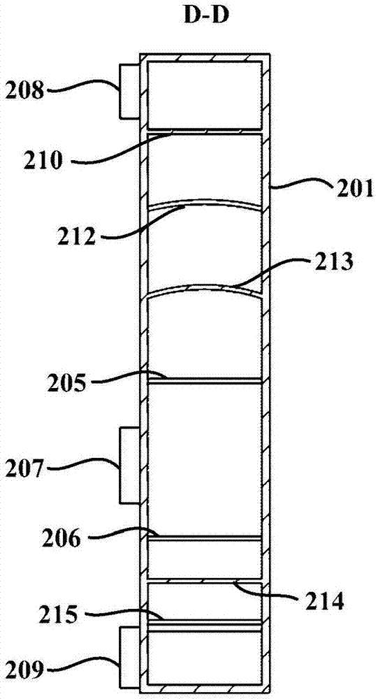
The invention provides a gas-liquid separator for a plate-type evaporator and the plate-type evaporator. The gas-liquid separator for the plate-type evaporator comprises a shell, a longitudinal separation plate, a first separation plate, a second separation plate, a liquid inlet pipe connection end, a gas outlet pipe connection end and a liquid outlet pipe connection end, wherein the longitudinal separation plate divides the internal space of the shell into two parts including a gas-liquid separation cavity and a liquid storage cavity; the gas-liquid separation cavity is divided into a gas separation region, a jetting region and a liquid separation region from top to bottom through the first separation plate and the second separation plate; the liquid inlet pipe connection end communicates with the jetting region and the exterior of the shell and is used for connecting a liquid inlet pipe which supplies refrigerating fluid to the plate-type evaporator; the gas outlet pipe connection end communicates with the gas separation region and the exterior of the shell and is used for connecting a gas outlet pipe which discharges gaseous refrigerating fluid to the exterior of the shell; and the liquid outlet pipe connection end communicates with the liquid separation region and the exterior of the shell and is used for connecting a liquid outlet pipe which conveys liquid refrigerating fluid to the plate-type evaporator. By means of the scheme, the situation that the gaseous refrigerating fluid enters the evaporator, and consequently the effective heat exchanging area of the evaporator is reduced, and the heat exchanging efficiency of the plate-type evaporator is effectively improved.

Description

Technical field [0001] The invention relates to the field of refrigeration systems, in particular to a gas-liquid separator and a plate evaporator used in a plate evaporator. Background technique [0002] With the increasing development of society and the continuous improvement of people's living standards, environmental regulation appliances such as air conditioners have become more and more popular, and air conditioners have become indispensable household appliances in people's lives. [0003] In the refrigeration system of an air conditioner, the condenser, evaporator, compressor and throttle are the four essential components. Among them, the compressor compresses the refrigerant into a high-pressure and high-temperature liquid, the condenser cools the refrigerant into a high-pressure and normal-temperature liquid, the throttle valve throttles and depresses the refrigerant into a normal-temperature and low-pressure liquid, and the evaporator transports cold energy in the refrige...

Claims


Application Information

Patent Timeline
Patent Type & Authority Applications(China)
IPC IPC(8): F25B43/00F25B39/02
CPCF25B39/022F25B43/00F25B2500/09
Inventor 虞雪明
Owner 依米康冷元节能科技(上海)有限公司
Learn More