Measurement probe and bio-optical measurement system
An optical measurement system and measurement probe technology, which is applied in the field of measurement probes and biological optical measurement systems, can solve the problems of villi structure displacement, inability to obtain properties and states, etc.
- Summary
- Abstract
- Description
- Claims
- Application Information
AI Technical Summary
Problems solved by technology
Method used
Image
Examples
Embodiment approach 1
[0058] 〔Structure of a biological optical measurement system〕
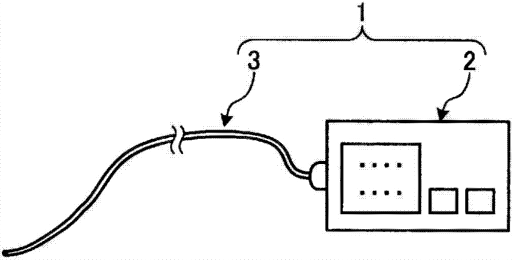
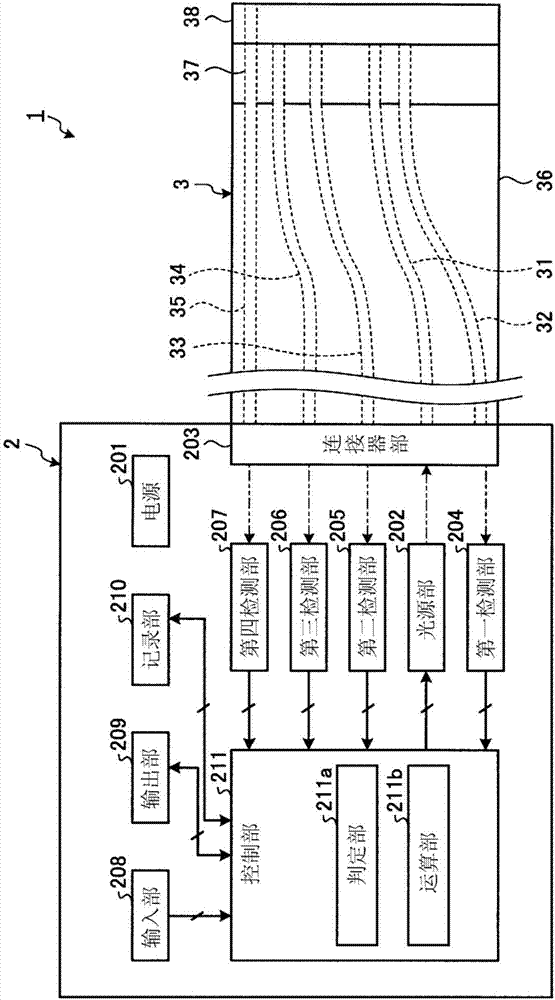
[0059] figure 1 It is a schematic diagram showing the configuration of the biological optical measurement system according to Embodiment 1 of the present invention. figure 2 It is a block diagram schematically showing the configuration of the biological optical measurement system according to Embodiment 1 of the present invention.
[0060] figure 1 and figure 2 The illustrated bio-optical measurement system 1 includes: a bio-optical measurement device 2 for optically measuring a measurement object such as a scatterer such as living tissue to detect the properties and states (characteristics) of the measurement object; and a measurement probe 3. It is detachably connected to the biological optical measurement device 2, and the front end side is inserted into the subject.
[0061] 〔Structure of a biological optical measurement device〕
[0062] First, the configuration of the bio-optical measurement device 2...
Embodiment approach 2
[0110] Next, Embodiment 2 of the present invention will be described. The biological optical measurement system according to Embodiment 2 differs in the configuration of the measurement probe from the configuration of the measurement probe according to Embodiment 1 described above. Specifically, the measurement probe according to Embodiment 2 includes a plurality of contact detection optical fibers. Therefore, the processing executed by the biological optical measurement system according to the second embodiment will be described below after describing the configuration of the measurement probe according to the second embodiment. In addition, the same reference numerals are assigned to the same configurations as those of the bio-optical measurement system 1 according to the above-mentioned first embodiment, and description thereof will be omitted.
[0111] 〔Structure of the measuring probe〕
[0112] Figure 11 It is a cross-sectional view of the measuring probe according to...
Embodiment approach 3
[0154] Next, Embodiment 3 of the present invention will be described. The configuration of the biological optical measurement system according to the third embodiment is different from the configuration of the biological optical measurement system 1 according to the above-mentioned first embodiment. Specifically, the biological optical measurement system according to Embodiment 3 further includes a light source unit for irradiating illumination light for detecting contact between the measurement probe and the object to be measured, and an illumination fiber. Therefore, the configuration of the biological optical measurement system according to Embodiment 3 will be described below. In addition, the same reference numerals are assigned to the same configurations as those of the bio-optical measurement system 1 according to the above-mentioned first embodiment, and description thereof will be omitted.
[0155] 〔Structure of a biological optical measurement system〕
[0156] Fi...
PUM
 Abstract
Description
Claims
Application Information
 - R&D
- Intellectual Property
- Life Sciences
- Materials
- Tech Scout
- Unparalleled Data Quality
- Higher Quality Content
- 60% Fewer Hallucinations
Browse by: Latest US Patents, China's latest patents, Technical Efficacy Thesaurus, Application Domain, Technology Topic, Popular Technical Reports.
© 2025 PatSnap. All rights reserved.Legal|Privacy policy|Modern Slavery Act Transparency Statement|Sitemap|About US| Contact US: help@patsnap.com


