
Device and method for producing a spring wire, device and method for marking a spring wire, device and method for producing springs from a spring wire, and spring wire

A spring steel wire and equipment technology, applied in the field of spring steel wire, can solve the problems of time and manpower waste, spring steel wire cannot be fully identified or identified, separated, etc., and achieve the effect of marking safety

Active Publication Date: 2017-08-01
SCHERDEL INNOTEC FORSCHUNGS UND ENTWICKLUNGS
View PDF7 Cites 0 Cited by
  • Summary
  • Abstract
  • Description
  • Claims
  • Application Information

AI Technical Summary

Problems solved by technology

During this process, defects or imperfections may develop in or on the spring wire which are often not adequately identified or identified
[0003] In the further processing of such spring steel wires to form springs, the production process would often have to be stopped due to such wire defects, and the defective areas had to be separated, resulting in a high waste of time and manpower

Method used


Image

  • Device and method for producing a spring wire, device and method for marking a spring wire, device and method for producing springs from a spring wire, and spring wire
  • Device and method for producing a spring wire, device and method for marking a spring wire, device and method for producing springs from a spring wire, and spring wire
  • Device and method for producing a spring wire, device and method for marking a spring wire, device and method for producing springs from a spring wire, and spring wire

Examples


Embodiment Construction

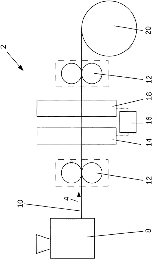
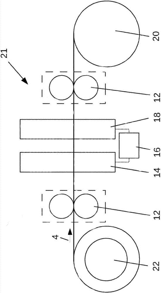
[0106] figure 1 A schematic diagram of a spring wire production plant 2 is shown.

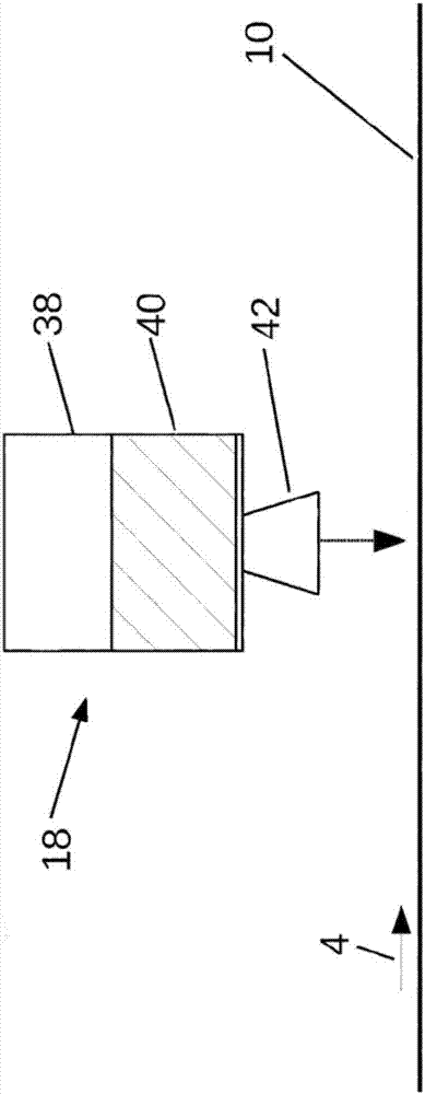
[0107] The spring steel wire production plant 2 comprises a wire production device 8 , a first wire guide 12 , a detection unit 14 , a laser marking unit 18 , a control unit 16 , an additional wire guide 12 and a take-up roller 20 .

[0108] The wire production device 8 is designed such that a spring steel wire 10 can be produced from raw material, in particular by drawing. This is well known to those skilled in the art and does not require a more detailed explanation here.

[0109] Spring steel wire 10 is produced continuously by wire production device 8 and toward figure 1 The right side leaves the wire production device 8 and passes through the first wire guide 12 , the detection unit 14 , the laser marking unit 18 , and the additional wire guide 12 , and finally winds into the take-up roller 20 . The direction of movement of the spring steel wire 10, which is at figure 1 From left to ri...


PUM

PropertyMeasurementUnit
diameteraaaaaaaaaa
depthaaaaaaaaaa
depthaaaaaaaaaa

Abstract

The invention relates to a device for producing a spring wire (2) comprising: a wire production apparatus (8), which is designed in such a way that a spring wire (10) can be produced from a raw material, in particular by drawing; a checking unit (14), which is designed in such a way that the spring wire (10) can be checked for flaws, in particular material flaws and surface flaws; and a laser marking unit (18), which is designed in such a way that flawed regions of the spring wire (10), in particular regions of the spring wire (10) having material flaws and surface flaws, can be marked with a laser marking (44) in such a way that a part of the surface of the spring wire (10) can be removed and that a part of the surface of the spring wire (10) can be tempered in such a way that the color of the surface of the spring wire (10) is changed in this part. The wire production apparatus (8) is designed in such a way that the spring wire (10) can be guided past the checking unit (14) and past the laser marking unit (18).

Description

technical field [0001] The present invention relates to an apparatus and method for producing spring steel wire, an apparatus and method for marking spring steel wire, an apparatus and method for producing springs from spring steel wire, and spring steel wire. Background technique [0002] Spring steel wire is currently produced in a continuous process by production equipment. During this process, defects or imperfections may develop within or on the surface of the spring wire which are often not adequately identified or identified. [0003] In the further processing of such spring steel wires to form springs, the production process would often have to be stopped due to such wire defects and the defective areas had to be separated, resulting in a high waste of time and manpower. Contents of the invention [0004] It is therefore an object of the present invention to provide a more efficient method and apparatus to achieve a higher spring production capacity and a process ...

Claims


Application Information

Patent Timeline
Patent Type & Authority Applications(China)
IPC IPC(8): B21C1/00B21C37/04B21C51/00B21F35/00B21F99/00F16F1/02
CPCB21C1/003B21C37/04B21C51/005B21F35/00B21F99/00F16F1/02F16F2226/02B23K26/361B21C37/045B21F35/02B23K26/0823B23K26/362F16F1/10F16F1/14F16F1/145F16F2226/023
Inventor 马库斯·巴赫马尔科·鲍尔
Owner SCHERDEL INNOTEC FORSCHUNGS UND ENTWICKLUNGS
Learn More