Turbine power generation system having emergency operation means, and emergency operation method therefor

一种发电系统、运转装置的技术,应用在安全装置、蒸汽机装置、喷气推进装置等方向,能够解决没有提及等问题,达到减少人力、维持健全性的效果

Inactive Publication Date: 2017-08-01
POSCO ENERGY CO LTD
View PDF4 Cites 2 Cited by
  • Summary
  • Abstract
  • Description
  • Claims
  • Application Information

AI Technical Summary

Problems solved by technology

[0024] However, as mentioned above, there is no mention in the prior art of a method that can solve the heat load problem in the condenser or the condenser when only the turbine stops working when it is suitable for a turbine power generation system. device

Method used


Image

  • Turbine power generation system having emergency operation means, and emergency operation method therefor
  • Turbine power generation system having emergency operation means, and emergency operation method therefor
  • Turbine power generation system having emergency operation means, and emergency operation method therefor

Examples


Embodiment Construction

[0055] The specific structures and functional descriptions mentioned in the embodiments of the present invention are merely exemplified to illustrate embodiments based on the concept of the present invention, and the embodiments based on the concept of the present invention can be implemented in various forms. In addition, it should not be construed as being limited to the embodiments described in this specification, but should be understood to include all modifications, equivalents, and substitutes included in the spirit and technical scope of the present invention.

[0056] Hereinafter, the present invention will be described in detail with reference to the accompanying drawings.

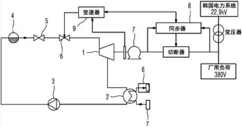
[0057] Figure 6 and Figure 7 The present invention is shown in, Figure 6 is a structural diagram showing a preferred embodiment of the present invention, Figure 7 It is a block diagram showing the procedure of the emergency operation method of the turbine power generation system of the pres...


PUM


Abstract

The present invention relates to a turbine power generation system having an emergency operation means capable of controlling and recycling the excessive amount of heat accumulated at the time of an emergency operation caused by a device malfunction, and an emergency operation method therefor. The turbine power generation system includes a steam turbine, a condenser, a compression pump, a heater, an inlet valve, and a proportional control valve which are sequentially connected and form a closed loop, and the turbine power generation system comprises a synchronizer and a governor which enable the amount of a working fluid, which flows through the closed loop, to be controlled by the inlet valve and the proportional control valve according to the number of rotations per unit hour of the steam turbine. The turbine power generation system comprises: an inlet sensor part which is installed between the heater and the inlet valve and includes a thermometer, a pressure gauge and a flowmeter; a branch pipe which branches from one point between the inlet sensor part and the inlet valve and is connected to the condenser; and a heat control means installed in the branch pipe. The heat control means comprises a heat storage valve, a heat storage device, and a discharge valve which are sequentially installed in the branch pipe from the one point, wherein the heat storage device comprises a heat exchanger so that the heat amount exchanged in the heat storage device is transferred to a heat consuming facility. Accordingly, the turbine power generation system having an emergency operation means of the present invention can reduce thermal overload during an emergency operation caused by a device malfunction of the turbine power generation system, minimize thermal consumption by means of recycling, and prevent various problems caused by interruption to the operation of the turbine power generation system.

Description

technical field [0001] The present invention relates to a turbine power generation system with an emergency operation device and its emergency operation method, in particular to a turbine power generation system with an emergency operation device capable of controlling and reusing excessive accumulated heat during emergency operation due to abnormal equipment and its emergency operation method. Background technique [0002] Control of systems that use steam energy to spin turbines to generate electricity can be roughly divided into two approaches. The first is a way of controlling the running turbine speed and the active and reactive power generated by the turbine, etc. [0003] The second is a system control method when an equipment failure is sensed due to abnormal temperature, pressure, and flow rate of the working fluid at the inlet of the turbine. [0004] The first control method is usually performed by using a transmission (governor) and a synchronizer. However, sa...

Claims


Application Information

Patent Timeline
Patent Type & Authority Applications(China)
IPC IPC(8): F01D15/10F01K11/02F01K13/02
CPCF01D15/10F01K11/02F01K13/02F01D17/08F01D17/105F01D21/003F05D2220/60F05D2220/72F05D2270/09F05D2270/301F05D2270/303F05D2270/3061F22B37/42F01K13/00F01K17/00F01K17/04F01K17/06F01K19/00F01K21/00F02C1/105F02C6/18F02C9/18
Inventor 吴星瑾李在俊任周昌李相勋李相明金基太河用植金哲圭
Owner POSCO ENERGY CO LTD
Why Eureka
Try Eureka