Connection arrangement comprising a hydraulic connection element

一种连接元件、连接组件的技术,应用在连接组件,内燃机上的装置领域,达到改善工作方式、节省构件、减小噪声的效果

Pending Publication Date: 2017-08-01
ROBERT BOSCH GMBH
View PDF7 Cites 0 Cited by
  • Summary
  • Abstract
  • Description
  • Claims
  • Application Information

AI Technical Summary

Problems solved by technology

[0003] The disadvantage of the sealing arrangement known from DE 10 2007 019 464 A1 is that additional components are required for hydraulic coordination

Method used


Image

  • Connection arrangement comprising a hydraulic connection element
  • Connection arrangement comprising a hydraulic connection element
  • Connection arrangement comprising a hydraulic connection element

Examples


Embodiment Construction

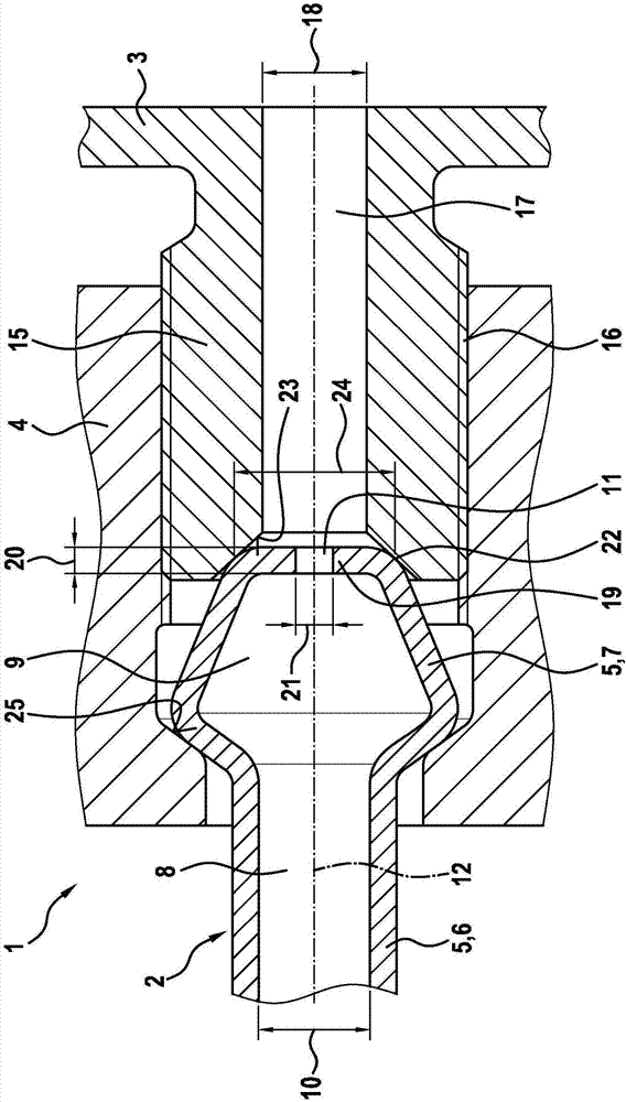
[0023] figure 1 Corresponding to the first exemplary embodiment, a connection assembly 1 is shown in a schematic axial section with a hydraulic connection element 2 and a hydraulic connection piece 3 . In this exemplary embodiment, fastening means 4 are also provided in order to pretension the connection.

[0024] The connection assembly 1 is particularly suitable for installation on internal combustion engines. In particular fuel can be conducted here via the hydraulic connection element 2 and the hydraulic connection piece 3 . However, the connection assembly 1 is also suitable for other applications using hydraulic media.

[0025] The hydraulic connection element 2 has a base body 5 with a pipe 6 and a tulip 7 attached to the pipe 6 . During production, the tulip-shaped part 7 can be formed in a suitable manner from the tubular base body 5 . A channel 8 in the form of a hole 8 is formed in the tube 6 , to which channel the interior 9 of the tulip-shaped part 7 is attach...


PUM


Abstract

A connection arrangement (1) comprises a hydraulic connection element (2) and a hydraulic connection piece (3), between which a seal is formed. The hydraulic connection element (2) has a base body (5) which comprises a tubular piece (6) and a tulip (7) attached to the tubular piece (6). In this way, an axial opening (11) is provided, via which a hydraulic medium, which can be guided over the tubular piece (6) via the tulip (7), can be guided out of the tulip (7) of the base body (5). The base body (5) is configured on the axial opening (11) in such a way that, during operation, a pressure drop is achieved in the hydraulic medium via the axial opening (11).

Description

technical field [0001] The invention relates to a hydraulic connection element, in particular for a device on an internal combustion engine, and to a connection assembly with such a hydraulic connection element and with a hydraulic connection part, in which the hydraulic connection element and the hydraulic connection part Guaranteed to be sealed. Background technique [0002] A sealing device for fuel line connections is known from DE 10 2007 019 464 A1. The known sealing device has a connection element of the fuel line and a receiving element for the connection element. A sealing element sleeve is also provided here, which is arranged between the connection element and the receiving element. The joint element has a ball element with an axial through passage. [0003] A disadvantage of the sealing arrangement known from DE 10 2007 019 464 A1 is that additional components are required for hydraulic coordination. Such hydraulic coordination, for example in injection syste...

Claims


Application Information

Patent Timeline
Patent Type & Authority Applications(China)
IPC IPC(8): F16L19/02F02M55/00
CPCF02M55/005F16L19/02F02M55/025F02M61/168
Inventor K·朗
Owner ROBERT BOSCH GMBH
Why Eureka
Try Eureka