Side-coated heat shield element with impingement cooling at exposed surfaces

A technology of heat shielding and components, which is applied in the field of manufacturing heat shielding components and heat shielding devices, can solve problems such as damage to the uniform distribution of cooling air, achieve cost-effective, avoid peeling, and achieve simple effects

Inactive Publication Date: 2017-08-01
SIEMENS AG
View PDF10 Cites 1 Cited by
  • Summary
  • Abstract
  • Description
  • Claims
  • Application Information

AI Technical Summary

Problems solved by technology

[0006] However, this embodiment has been found to have a disadvantage: when the heat shield elements are arranged next to each other, cooling air exiting through the cooling air holes of one heat shield element encounters head-on the cooling air holes of the adjacent heat shield element cooling air leaving
This impairs the even distribution of cooling air over the length of the lateral gap

Method used


Image

  • Side-coated heat shield element with impingement cooling at exposed surfaces
  • Side-coated heat shield element with impingement cooling at exposed surfaces
  • Side-coated heat shield element with impingement cooling at exposed surfaces

Examples


Embodiment Construction

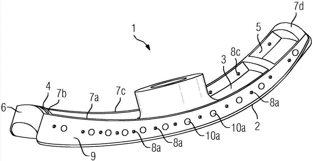
[0036] figure 1 A first exemplary embodiment for a heat shield element 1 according to the invention is shown schematically and by way of example. The heat shield element 1 is substantially metallic, ie it comprises a metal body. It has a hot side 2 that can be exposed to the heat medium and a cold side 3 opposite the hot side 2 . Adjacent the hot side 2 and the cold side 3 is a peripheral edge 4 extending beyond the face of the cold side 3 with an inner side 5 and an outer side 6 and a plurality of edge sections 7a, 7b, 7c and 7d. In the rim 4 , cooling air openings 8 a are arranged in the rim section 7 a and cooling air openings 8 c are arranged in the rim section 7 c , each extending from the inner side 5 to the outer side 6 . The arrangement of the cooling air openings 8a, 8c is selected such that the cooling air opening 8a of the edge section 7a is arranged offset relative to the cooling air opening 8c of the opposite edge section 7c. According to the invention, the out...


PUM


Abstract

The invention relates to a heat shield element (1) and a heat shield arrangement (11) for lining a combustion chamber wall, wherein the heat shield element (1) has a hot side (2) which can be contacted by a hot medium and a cold side (3) lying opposite the hot side (2) and a circumferential edge (4) adjoining the hot side (2) and the cold side (3). The edge (4) extends past the plane of the cold side (3) and has, at least in sections, a plurality of cool air openings (8a, 8c), wherein the cool air openings (8a) of an edge section (7a) of a heat shield element (1) are arranged offset to the cool air openings (8c) in the edge section (7c) of the adjacent head shield element (1). The invention further relates to a method for producing a heat shield element (1).

Description

technical field [0001] The invention relates to a heat shielding element, in particular for cladding a combustion chamber wall, and to a heat shielding arrangement consisting of a heat shielding element. The invention also relates to a method for producing a heat shield element. Background technique [0002] In order to protect the structure of the combustion chamber from high temperatures, it can be clad, for example, with ceramic tiles (ceramic heat shield) and / or metal tiles (metal heat shield). The heat shield element generally has a planar form with a hot side facing the combustion chamber and an opposite cold side and a peripheral rim, wherein a plurality of heat shield elements arranged next to each other form a heat shield. In this context, the heat shield elements are positioned at a distance from one another so as to form a lateral gap in each case between the edges of adjacent heat shield elements. [0003] Very high thermal loads during operation of the gas tur...

Claims


Application Information

Patent Timeline
Patent Type & Authority Applications(China)
IPC IPC(8): F23R3/00F23R3/60
CPCF23R3/005F23R3/007F23R3/60F23R2900/00012F23R2900/03042F23R2900/03043
Inventor A·伯切尔C·格兰特A·克卢格T·克里格K-U·席尔德马彻
Owner SIEMENS AG
Why Eureka
Try Eureka