Overlapped-type casting method of large-size annular steel casting
A steel casting, superimposed technology, applied in the direction of casting molding equipment, casting molds, casting mold components, etc., can solve the problems of large amount of molding sand, low molding efficiency, high cost of pattern production, etc., to reduce casting costs and improve production efficiency effect
- Summary
- Abstract
- Description
- Claims
- Application Information
AI Technical Summary
Problems solved by technology
Method used
Image

Examples
Embodiment Construction
[0032] In order to more clearly illustrate the technical solutions of the embodiments of the present invention, the following will briefly introduce the accompanying drawings that need to be used in the embodiments. Obviously, the accompanying drawings in the following description are some embodiments of the present invention. Ordinary technicians can also obtain other drawings based on these drawings on the premise of not paying creative work.
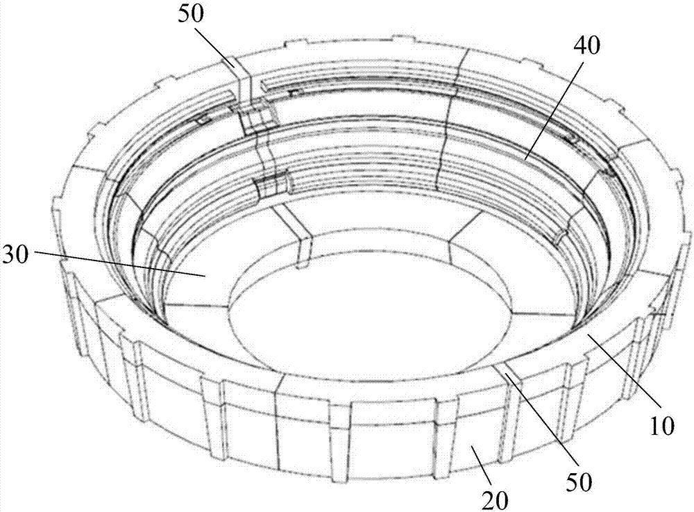
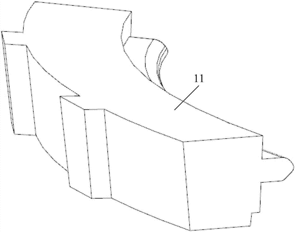
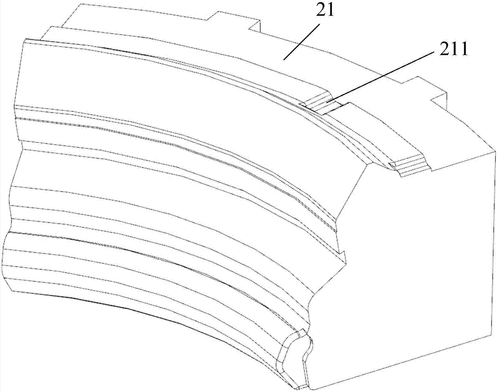
[0033] An embodiment of the present invention provides a superimposed casting method for a large-size annular steel casting, which includes the following steps:
[0034] see Figure 1 to Figure 4 , core making: utilize core box to prepare the sand core of superimposed casting, the sand core of described superimposed casting comprises the first sand core 10, the second sand core 20, the third sand core 30 that are arranged from top to bottom, the second The sand core 20 also includes an upper and lower partition sand core 40, the uppe...
PUM
 Abstract
Description
Claims
Application Information
 - R&D
- Intellectual Property
- Life Sciences
- Materials
- Tech Scout
- Unparalleled Data Quality
- Higher Quality Content
- 60% Fewer Hallucinations
Browse by: Latest US Patents, China's latest patents, Technical Efficacy Thesaurus, Application Domain, Technology Topic, Popular Technical Reports.
© 2025 PatSnap. All rights reserved.Legal|Privacy policy|Modern Slavery Act Transparency Statement|Sitemap|About US| Contact US: help@patsnap.com