
Automatic double-layer plate separator and working method thereof

A splitting machine, double-layer technology, applied in the direction of manufacturing tools, metal processing equipment, metal processing machinery parts, etc., can solve the problems of increasing labor intensity of operators, affecting operation efficiency, low milling precision, etc., and achieves a fixed effect Good, good protection effect, high work efficiency

Inactive Publication Date: 2017-08-04
VECTRON TECH ELECTRONICS EQUIP
View PDF8 Cites 3 Cited by
  • Summary
  • Abstract
  • Description
  • Claims
  • Application Information

AI Technical Summary

Problems solved by technology

The existing circuit board splitters are generally divided into manual and automatic. For the manual knife type PCB board splitter, the operator puts the circuit board to be split on the knife holder, and then slides the cutter along the slide rail. Come over, and complete the board splitting operation with the sliding of the cutter; but after the cutter slides to one end of the slide rail to complete a board splitting operation, since the operator is operating the circuit board with one hand and sliding the cutter with the other hand, it is always It is necessary to move the cutter back to the original position before performing the next splitting operation. Such a manual reset operation is time-consuming and laborious, which directly affects the overall work efficiency of the operation and increases the labor intensity of the operator.
[0003] Most of the existing automatic splitting machines have certain disadvantages, such as low work efficiency and low milling precision, which need to be solved

Method used


Image

  • Automatic double-layer plate separator and working method thereof
  • Automatic double-layer plate separator and working method thereof
  • Automatic double-layer plate separator and working method thereof

Examples


Embodiment Construction

[0058] The present invention will be further described below in conjunction with the accompanying drawings.

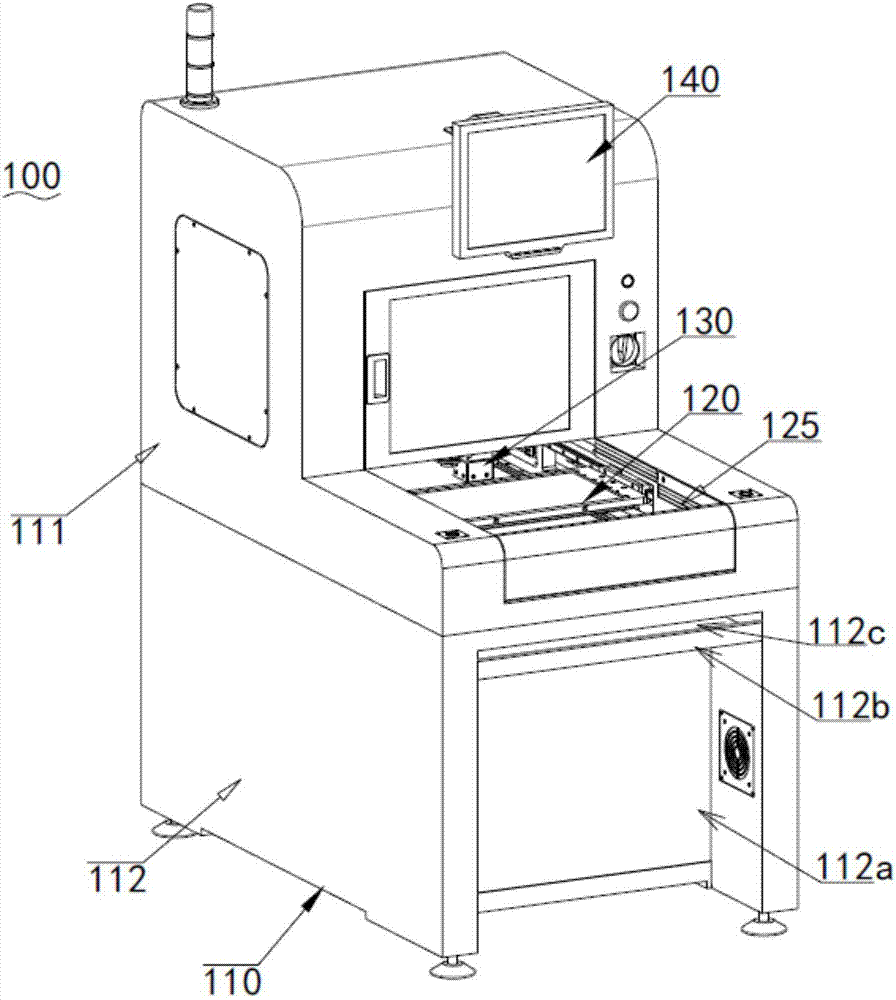
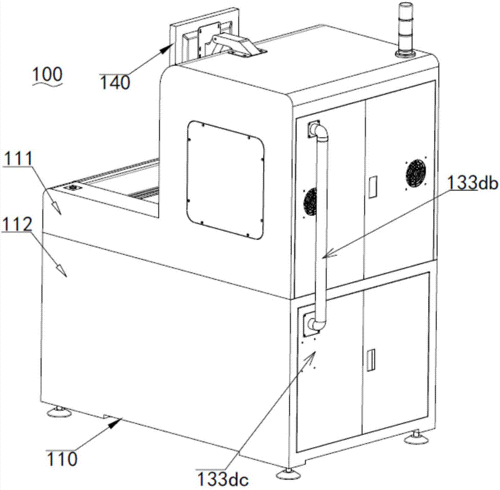
[0059] Such as Figure 1 ~ Figure 2 Shown are respectively the perspective views of different viewing angles of the present invention.

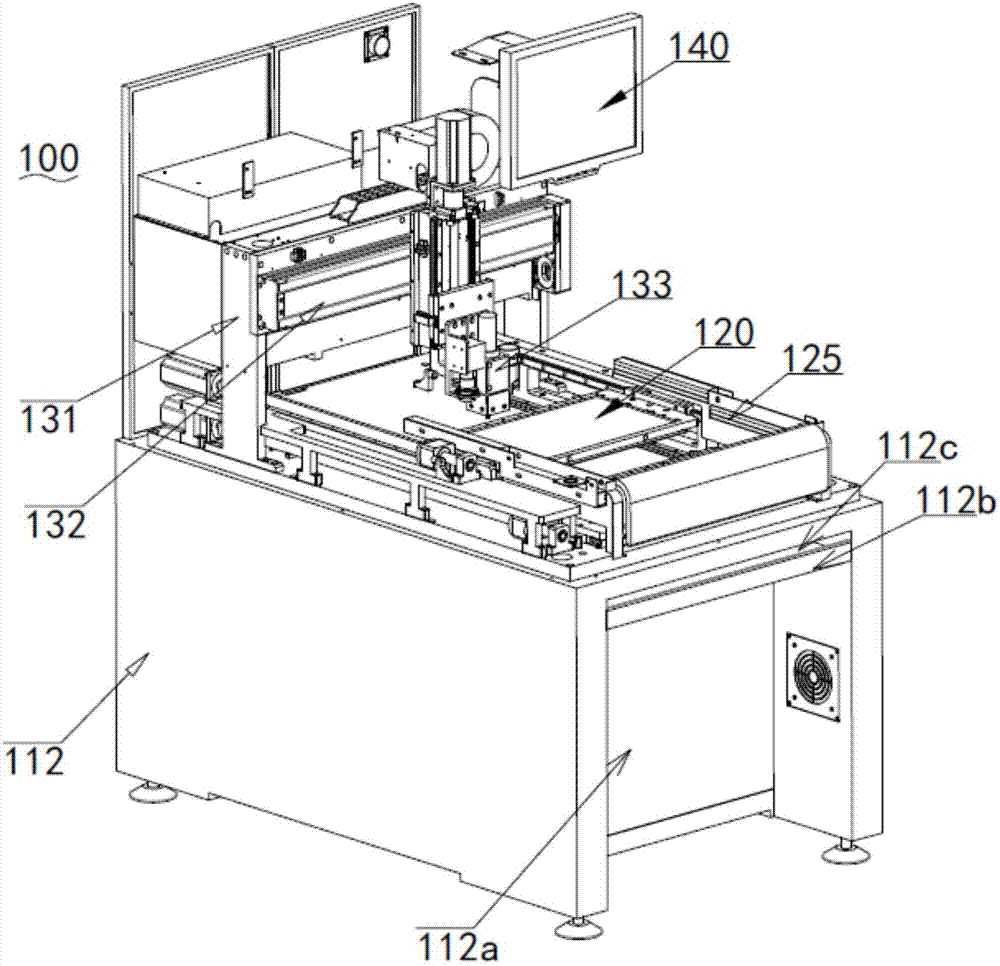
[0060] Such as image 3 Shown is a perspective view of the present invention with the upper frame removed.

[0061] A kind of double-deck automatic plate splitter 100, comprises frame 110, workbench 120, cutting device 130 and control device 140; Described frame 110 comprises upper frame body 111 and lower frame body 112, and described workbench 120 and cutting device 130 are installed on the lower frame body 112, the control device 140 is electrically connected with the workbench 120 and the cutting device 130, the control device 140 is installed on the upper frame body 111, and the upper frame body 111 is installed on the lower frame body 112 and is covered On the workbench 120 and the cutting device 130, the workbench 120 is pro...


PUM


Abstract

The invention relates to the technical field of plate separation equipment, in particular to an automatic double-layer plate separator and a working method thereof. The plate separator comprises a frame, a worktable, a cutting device and a control device; the frame comprises an upper frame body and a lower frame body; the control device is electrically connected with the worktable and the cutting device; the worktable is provided with a first mounting table and a second mounting table; the first mounting table is positioned above the second mounting table; the first mounting table and the second mounting table are in reciprocating transmission below the cutting device; and two mounting tables are provided for fixing plates for reciprocating milling to achieve high working efficiency. The working method comprises the following steps: firstly, the plates are fixed on the worktable; procedures are written in the control device; a detecting module detects the positions of the plates; a milling tool module mills the plates; a dust sucking module sucks dust; and the detecting module detects the plates until the operation is completed. The automatic double-layer plate separator and the working method thereof can fix multiple plates on the worktable, mill multiple plates, and detect the milling effect by multiple times to achieve high milling precision.

Description

technical field [0001] The invention relates to the technical field of board splitting equipment, in particular to a double-layer automatic board splitting machine and a working method thereof. Background technique [0002] Circuit boards are necessary components in electronic products. In the production process of electronic products, circuit boards need to be divided by a splitter. The circuit board splitter is a kind of machine equipment that cuts off the ribs of multiple circuit boards (ie PCB boards) that are integrated to separate a single circuit board. The existing circuit board splitters are generally divided into manual and automatic. For the manual knife type PCB board splitter, the operator puts the circuit board to be split on the knife holder, and then slides the cutter along the slide rail. Come over, complete the circuit board splitting operation with the sliding of the cutter; but after the cutter slides to one end of the slide rail to complete a splitting ...

Claims


Application Information

Patent Timeline
Patent Type & Authority Applications(China)
IPC IPC(8): B23C3/00B23C9/00B23Q11/00B23Q17/22
CPCB23C3/00B23C9/00B23Q11/0046B23Q17/22
Inventor 蒋福瑛
Owner VECTRON TECH ELECTRONICS EQUIP
Learn More